
Sensor network system

a sensor network and sensor technology, applied in the field of systems, can solve problems such as troublesome correction of such errors, and achieve the effect of saving troubl

Active Publication Date: 2006-11-16
HITACHI LTD
View PDF9 Cites 37 Cited by
  • Summary
  • Abstract
  • Description
  • Claims
  • Application Information

AI Technical Summary

Benefits of technology

[0007] The present invention provides, without requiring the mechanism of sensor chips to be changed, a means for saving the trouble of mapping sensor information on a map information system.

Problems solved by technology

There are the following problems with the conventional technique.
Correcting such an error is troublesome.

Method used


Image

  • Sensor network system
  • Sensor network system
  • Sensor network system

Examples


Embodiment Construction

[0035] An embodiment in which the present invention is applied to a microtremor measurement system will be described in the following with reference to the accompanying drawings. By measuring microtremor on the ground surface using an acceleration sensor or a speed sensor, the amplification characteristic of earthquake motion at the location of the measurement can be evaluated. An amplification characteristic of earthquake motion is an important parameter for evaluating local geological vulnerability. The present embodiment makes it possible to evaluate geological vulnerability not only at a representative point of a region but at locations all over the region.

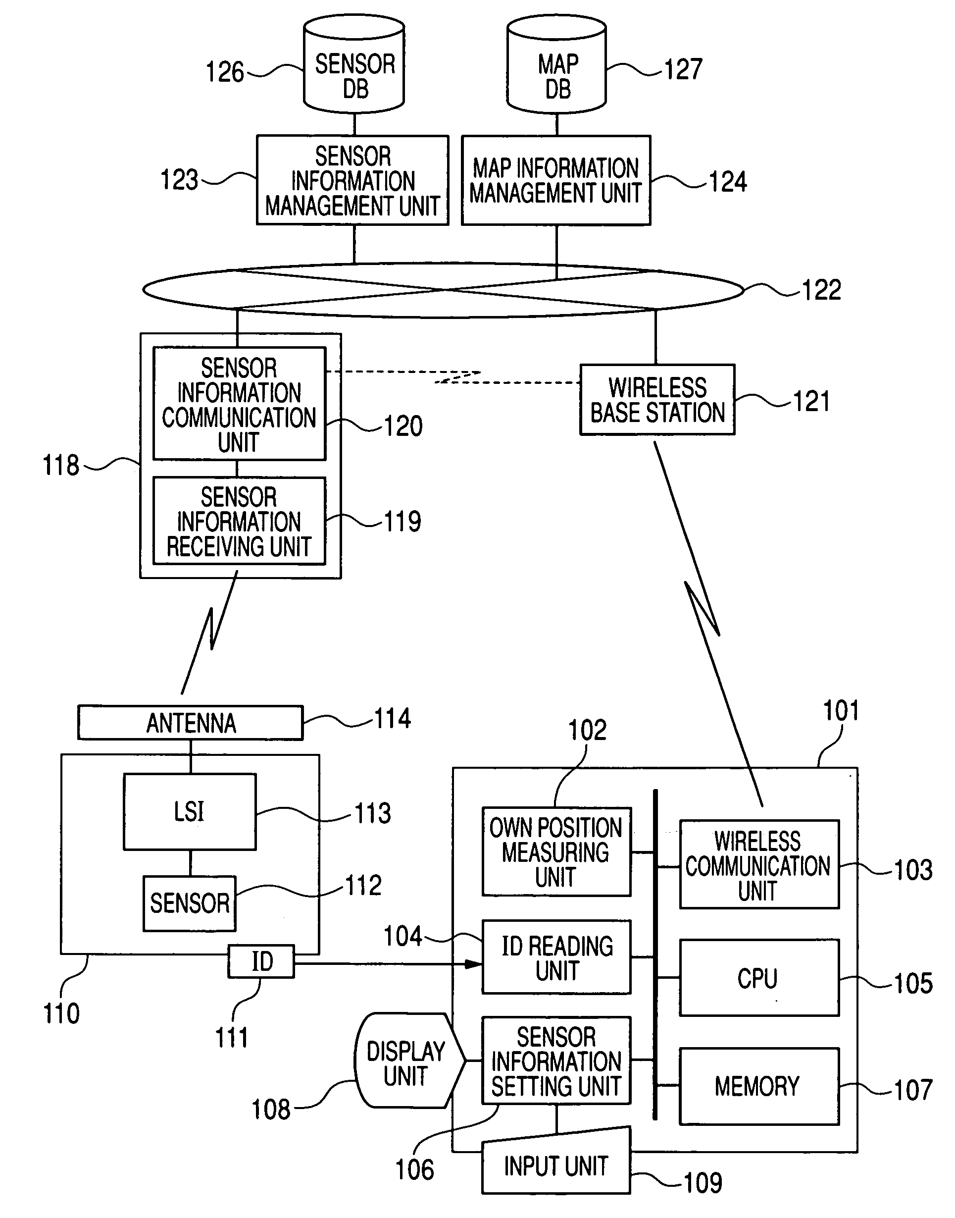
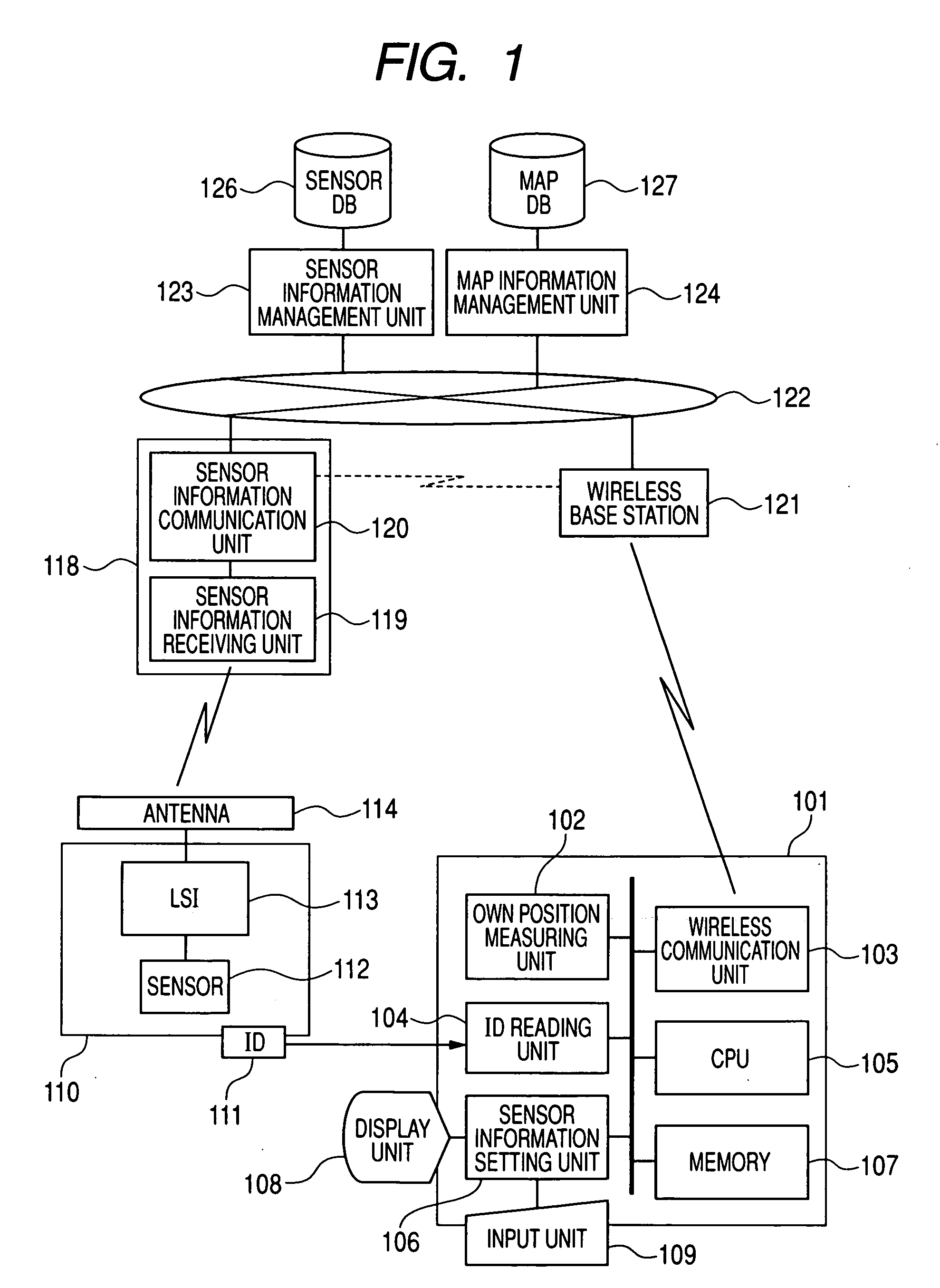
[0036]FIG. 1 shows an overall configuration of the system. A value measured by a sensor 112 included in a sensor chip 110 is received by a receiver 118 via wireless communication. The measured value is communicated to a sensor information management unit 123 and stored in a sensor DB 126. An ID 111 is attached to the sensor c...


PUM


Abstract

An object of the invention is to save the trouble of mapping sensor chips on a map information system. A map information management unit 124 is accessed via a network 122. Neighborhood information based on a present position measured by an own position measuring unit 102 is obtained by searching a map DB 127. A sensor information setting unit 106 displays the neighborhood information in a display unit 108. An ID reading unit 104 reads an ID 111 of a sensor chip 110, and registers the ID 111 in the map DB 127 after associating it with equipment information displayed in the display unit 108. The measurement values measured by a sensor 112 are transmitted from an antenna 114 and received by a sensor information receiving unit 119 of the receiver 118. A sensor information communication unit 120 accesses the network 122 and the measurements are transmitted to a sensor information management unit 123. The measurement values are accumulated in a sensor DB 126. The sensor DB 126 is searched using a sensor ID associated in the map DB 127 and the measurements are viewed as map information associated with equipment.

Description

TECHNICAL FIELD [0001] The present invention relates to a system for managing locations where IC chips with a built-in sensor are installed. More particularly, it relates to a sensor location management system suitable for an application in which IC chips are installed over a wide area and measurements obtained using built-in sensors are collected from the whole area. BACKGROUND ART [0002] Technology called MEMS (Micro Electro Mechanical System), which realizes functions of an electronic device on a micro IC chip, has been progressing remarkably in recent years. MEMS makes it possible to realize sensor chips having measurement and wireless communication functions. Measurements produced by such sensor chips can be collected by wireless communication. Such sensor chips can, therefore, be installed arbitrarily in diversified locations. They are expected to find applications where equipment management or environmental management is required to be more meticulous than before. [0003] When...

Claims


Application Information

Patent Timeline
IPC IPC(8): H04B17/00G01S1/00G01V1/00G06Q10/00G06Q50/00G06Q50/10G09B29/00H04M3/42H04M11/00H04W4/04H04W28/00H04W64/00H04W84/10H04W88/18
CPCG01V1/008G01V1/01
Inventor KATO, HIROMITSUMIYAO, TAKESHI
Owner HITACHI LTD
Learn More