Method of operating a memory cell

a memory cell and memory technology, applied in the field of semiconductor memory, can solve the problems of data corruption, high manufacturing cost as compared with dram, and gradual discharge of charg

Inactive Publication Date: 2006-11-23
MICRON TECH INC
View PDF18 Cites 23 Cited by
  • Summary
  • Abstract
  • Description
  • Claims
  • Application Information

AI Technical Summary

Problems solved by technology

After the data has been stored as charge on the capacitor, the charge gradually leaks off and the data is corrupted.
Along with the benefits of SRAM, however, comes a high manufacturing cost as compared with DRAM.

Method used


Image

  • Method of operating a memory cell
  • Method of operating a memory cell
  • Method of operating a memory cell

Examples


Embodiment Construction

[0012] In the following detailed description, reference is made to the accompanying drawings which form a part hereof, and in which is shown by way of illustration specific embodiments in which the invention may be practiced. These embodiments are described in sufficient detail to enable those of ordinary skill in the art to make and use the invention, and it is to be understood that structural, logical or procedural changes may be made to the specific embodiments disclosed without departing from the spirit and scope of the present invention.

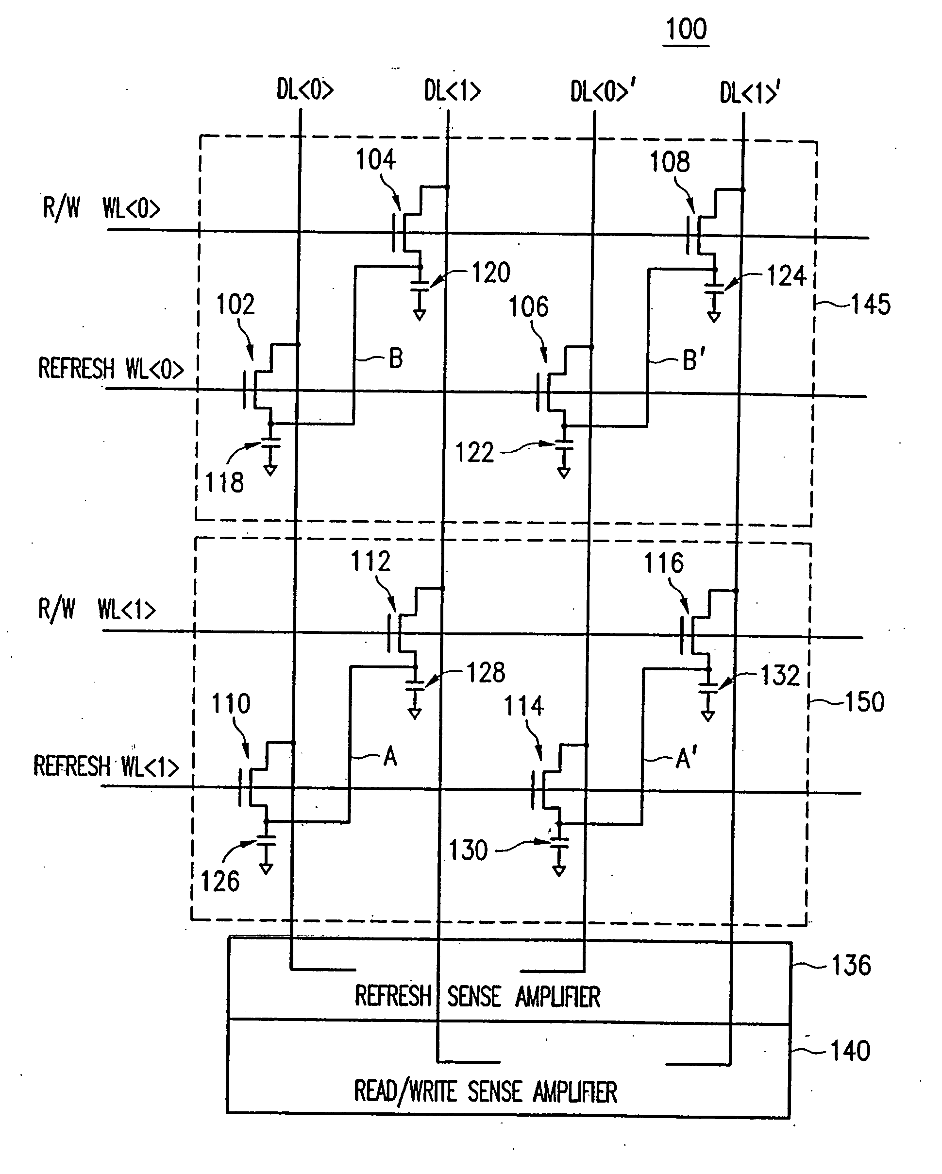
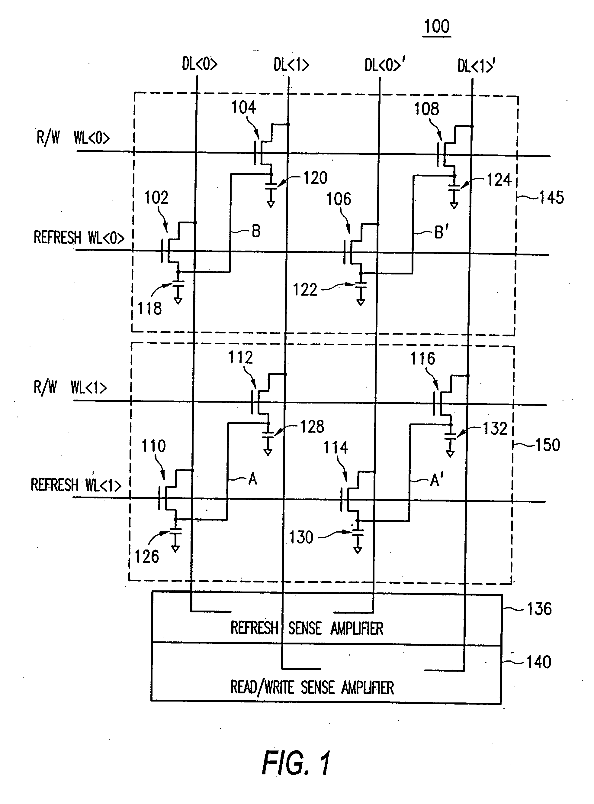
[0013]FIG. 1 depicts a simplified schematic diagram of a memory cell array 100 having two memory cells 145, 150 in accordance with an exemplary embodiment of the invention. The memory cell array consists of four digit lines DL, DL, DL′ and DL′ (depicted in the vertical direction) and four wordlines read / write wordline (R / W WL), refresh wordline (Refresh WL), R / W WL, and Refresh WL (depicted in the horizontal direction).

[0014] Turning first to...


PUM


Abstract

A method of operating a dynamic random access memory cell is disclosed. The true logic state of a stored bit is rewritten to a first storage node of the memory cell and the complementary logic state of the stored bit is rewritten to a second storage node of the memory cell. One of the acts of rewriting is achievable faster than the other and the rewriting of the true and complementary logic states is completed upon achieving the one act of rewriting that is faster than the other.

Description

[0001] This application is a divisional of application Ser. No. 10 / 969,184, filed Oct. 21, 2004, which is a divisional of application Ser. No. 10 / 436,166, filed May 13, 2003, which is a divisional of application Ser. No. 10 / 225,423, filed Aug. 22, 2002, the entire disclosure of each being incorporated herein by reference in its entirety.FIELD OF THE INVENTION [0002] The present invention relates generally to semiconductor memory, and more particularly to a high-speed dynamic random access memory (DRAM)-based memory cell having transparent refresh. BACKGROUND OF THE INVENTION [0003] In a dynamic random access memory (“DRAM”), data is stored as a logic HIGH (e.g., “1”) or logic LOW (e.g., “0”) by the presence or absence of charge on a capacitor within an individual memory cell. After the data has been stored as charge on the capacitor, the charge gradually leaks off and the data is corrupted. Therefore, a “refresh” cycle must be performed to maintain the integrity of the data. [0004] ...

Claims


Application Information

Patent Timeline
Patent Type & Authority Applications(United States)
IPC IPC(8): G11C7/00G11C11/405G11C11/406
CPCG11C11/404G11C11/405G11C2211/4065G11C11/40603G11C11/406
Inventor LOVETT, SIMON J.
Owner MICRON TECH INC
Why Eureka
Try Eureka