High density optical fiber distribution enclosure

a high-density, optical fiber technology, applied in the direction of optics, optical light guides, instruments, etc., can solve the problem that all functions are less than optimal in one or more of the desired attributes

Active Publication Date: 2006-11-23
CORNING OPTICAL COMM LLC
View PDF86 Cites 78 Cited by
  • Summary
  • Abstract
  • Description
  • Claims
  • Application Information

AI Technical Summary

Benefits of technology

[0011] In another aspect, the invention is an optical fiber distribution enclosure including a housing defining an interior and a longitudinal axis. The enclosure further includes a first fiber distribution area disposed within the interior of the housing and having a first fiber distribution field for optically connecting at least one of a plurality of splitter output optical fibers with a corresponding one of a plurality of optical fibers of a distribution cable. The fiber distribution field defines a first plane generally paralle

Problems solved by technology

While existing enclosures (including the LLC described in the '191 patent) satisfy at least some of the above objectives, all function less than optimally in one or more of the des

Method used


Image

  • High density optical fiber distribution enclosure
  • High density optical fiber distribution enclosure
  • High density optical fiber distribution enclosure

Examples


Embodiment Construction

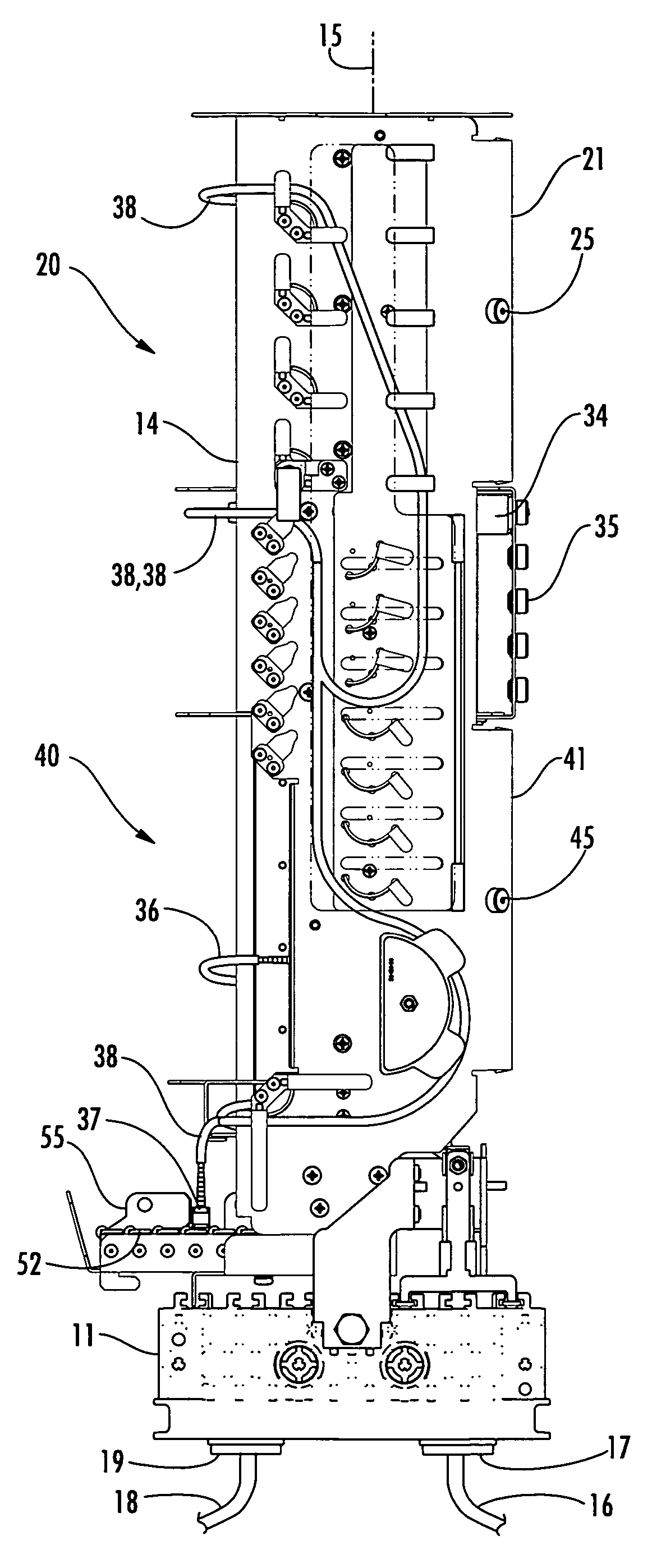
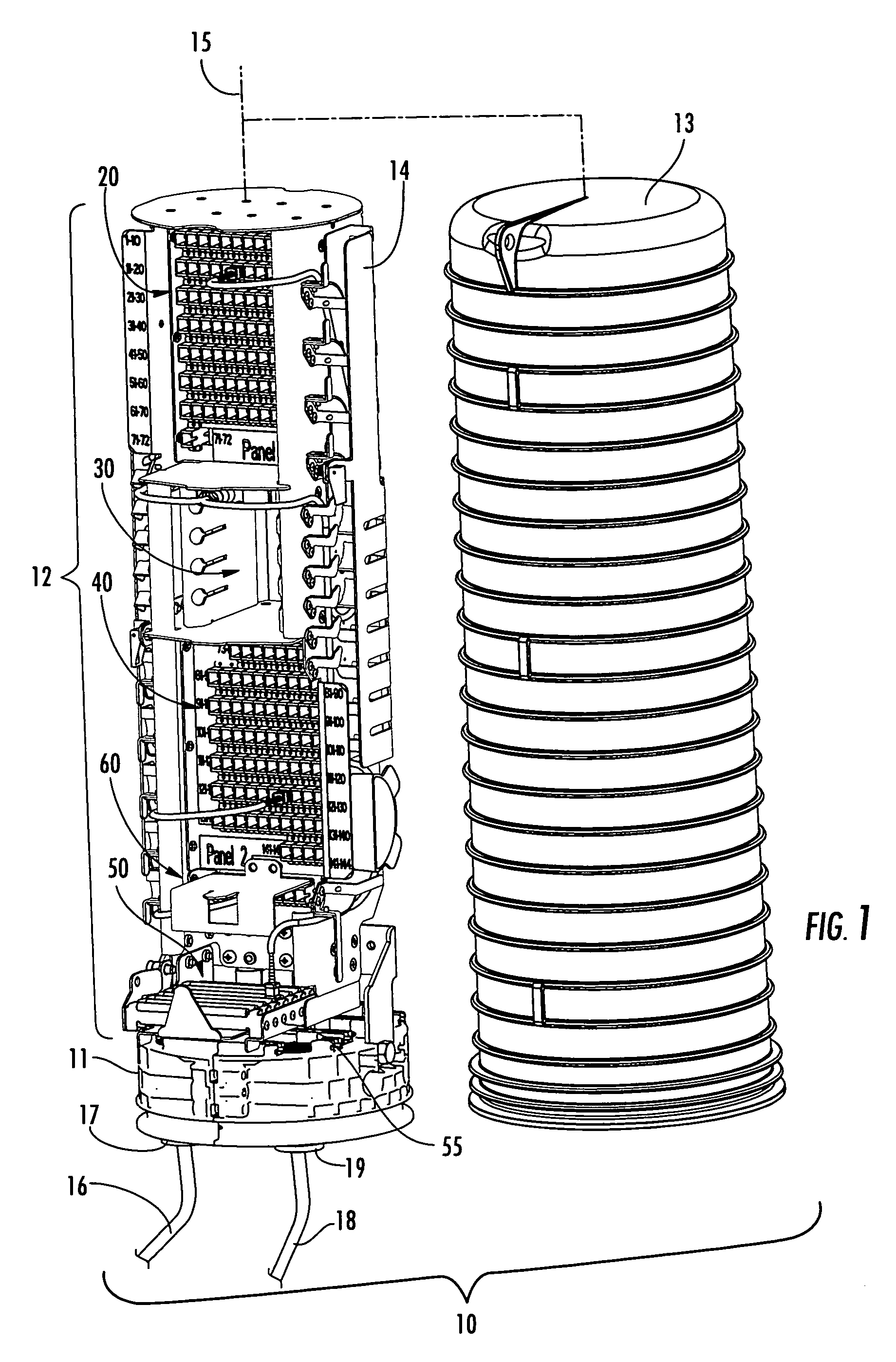
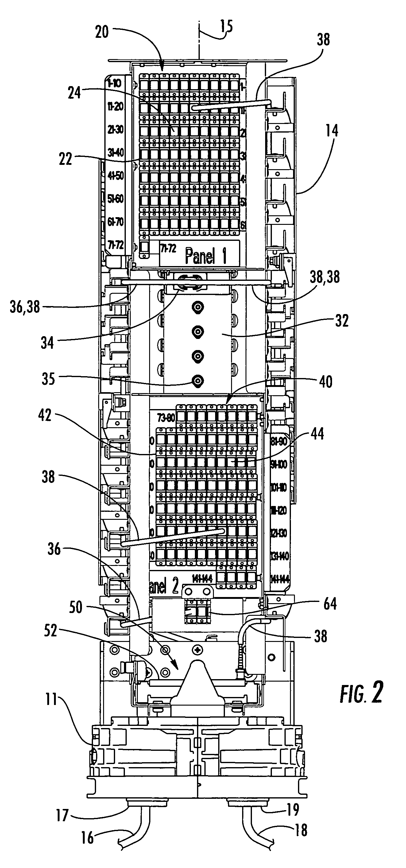
[0022] Reference will now be made in detail to exemplary and presently preferred embodiments of the invention, illustrations of which are provided in the accompanying drawings. Whenever possible, the same reference numerals are used throughout the drawings to refer to the same or similar parts. The present invention is an optical fiber distribution enclosure, sometimes referred to as a fiber distribution hub (FDH), a fiber distribution terminal (FDT) or a local convergence cabinet (LCC), for use in the outside plant of a passive optical network (PON) as an interface between a service provider of broadband optical communications and multiple subscribers. The optical fiber distribution enclosure is operable for splitting an optical signal carried on an optical fiber of a feeder cable into multiple optical signals carried on a plurality of optical fibers of one or more distribution cables, and for interconnecting connectorized output optical fibers from at least one splitter module wit...


PUM


Abstract

An optical fiber distribution enclosure includes a housing defining an interior, a first fiber distribution area disposed within an upper portion of the interior, a second fiber distribution area disposed within a lower portion of the interior and a signal splitting area disposed between the fiber distribution areas. A splitter module secured within the signal splitting area has a connectorized splitter input optical fiber and connectorized splitter output optical fibers. A fiber parking area is movably disposed within the lower portion adjacent the second fiber distribution area for temporarily storing splitter output optical fibers that are not routed to the fiber distribution areas. An input fiber distribution area disposed within the interior interconnects an optical fiber of a feeder cable with the splitter input optical fiber. The splitter output optical fibers are eventually routed to a fiber distribution area and interconnected with a corresponding optical fiber of a distribution cable.

Description

CROSS REFERENCE To RELATED APPLICATIONS [0001] This application claims the benefit of U.S. Provisional Application No. 60 / 682,307, filed on May 18, 2005, and entitled High Density Fiber Distribution Closure, the disclosure of which is incorporated herein in its entirety.BACKGROUND OF THE INVENTION [0002] 1. Field of the Invention [0003] The present invention relates generally to an optical fiber distribution enclosure for use in a passive optical network (PON), and more particularly, to a high density optical fiber distribution enclosure for splitting an optical signal carried on an optical fiber of a feeder cable into multiple optical signals carried on a plurality of optical fibers of a distribution cable in the outside plant of a PON. [0004] 2. Technical Background [0005] It is now well known to use an optical splitter or splitter module (sometimes also referred to as a coupler module) in the outside plant of a passive optical network (PON) to distribute a broadband optical commu...

Claims


Application Information

Patent Timeline
IPC IPC(8): G02B6/00
CPCG02B6/4442
Inventor MUDD, RONALD L.MCGRANAHAN, DANIEL S.CASTONGUAY, GUYWORKS, ANTWAN J.
Owner CORNING OPTICAL COMM LLC
Why Eureka
Try Eureka