
Doctor blade and development unit having the same

Inactive Publication Date: 2006-11-23
SAMSUNG ELECTRONICS CO LTD
View PDF3 Cites 14 Cited by
  • Summary
  • Abstract
  • Description
  • Claims
  • Application Information

AI Technical Summary

Benefits of technology

[0012] Accordingly, aspects of the present invention provide a solution to the above-mentioned and / or other problems, among other benefits. An aspect of the present invention provides a doctor blade of an image forming apparatus to uniformly maintain a contact pressure between an elastic blade and a developer roller to resolve uneven image concentration problems.
[0014] An aspect of the present invention provides a development unit having the doctor blade to uniformly maintain a contact pressure between an elastic blade and a developer roller to resolve uneven image concentration problems and improve image quality.
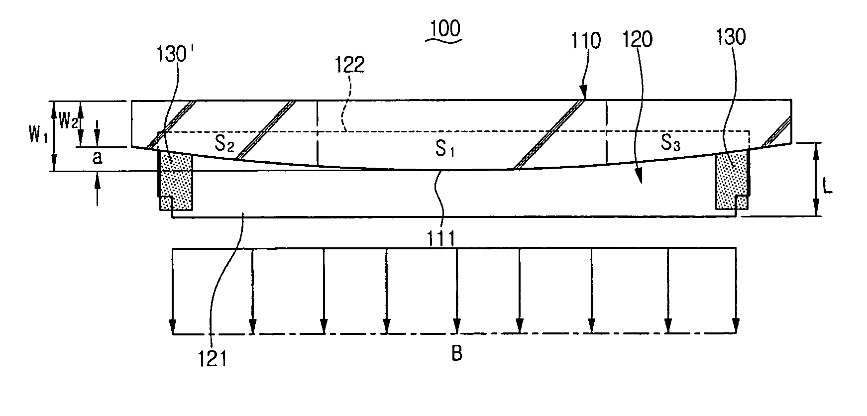
[0018] Another aspect of the present invention provides, a doctor blade of an image forming apparatus including: an elastic blade having one edge portion in contact with a rotating developer roller with a predetermined pressure to control a thickness of a toner layer on the developer roller; a supporting member supporting the other edge portion of the elastic member; and a seal member mounted on each end of the elastic blade to prevent leakage of the toner, wherein the size of the middle portion of the supporting member is larger than a size of each end portion of the supporting member to uniformly distribute contact pressure between the elastic blade and the developer roller along a length direction of the developer roller.
[0019] According to an aspect of the present invention, there is provided a development unit including: a developer roller rotatably arranged to face a photoconductor; an elastic blade having one edge portion in contact with the rotating developer roller to control a thickness of a toner layer on the developer roller; a supporting member supporting the other edge portion of the elastic blade, wherein one side of a middle portion of the supporting member may protrude along the elastic blade farther than each end portion of the supporting member by a predetermined distance to exert a higher elastic stress in the elastic blade along the middle portion to cause the contact pressure between the elastic blade and the developer roller to be uniform along the length of the developer roller; and seal members respectively mounted at each end of the elastic blade to prevent leakage of the toner.

Problems solved by technology

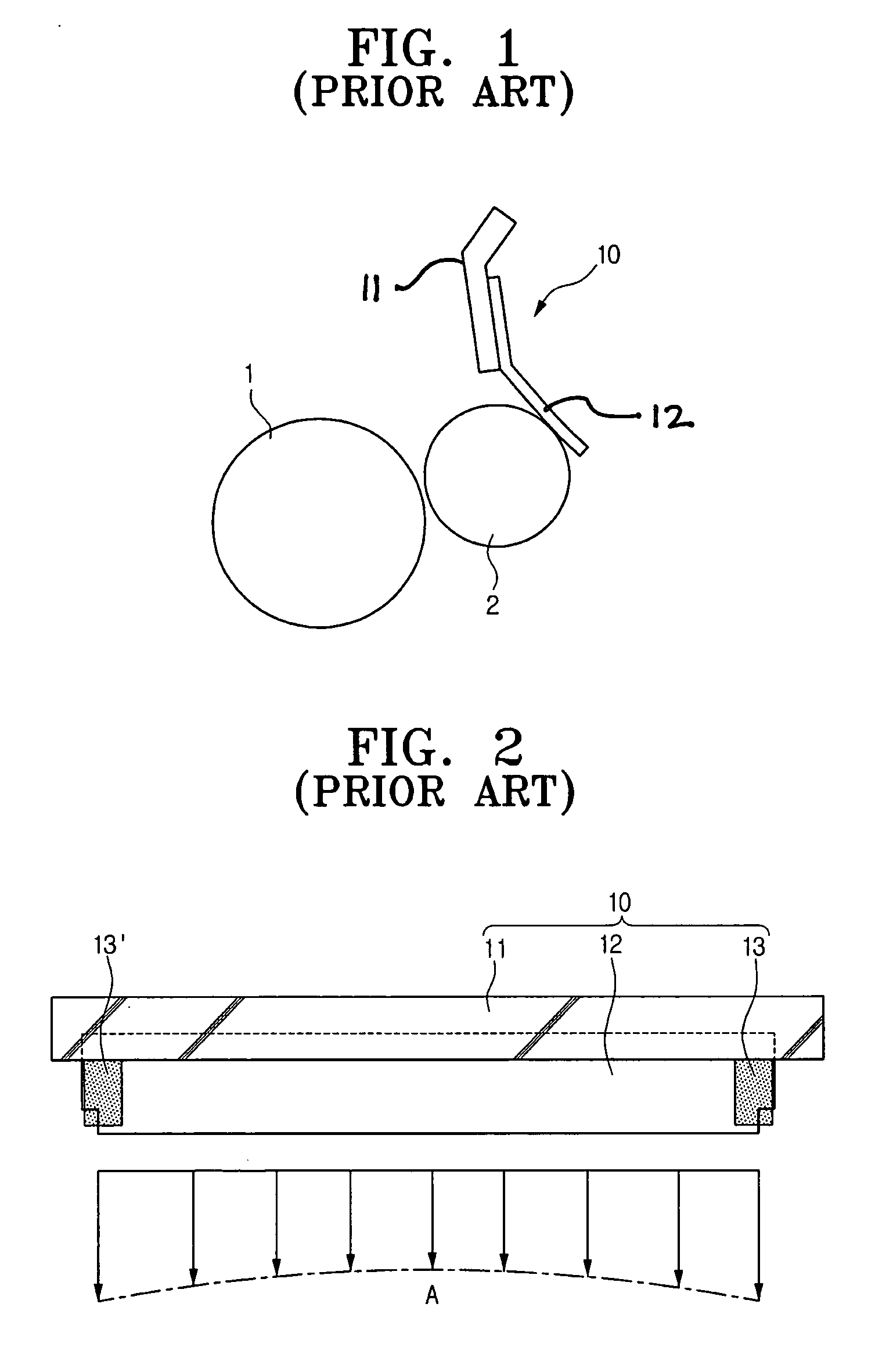
As a result, concentration of toner across an image formed on the print medium becomes uneven giving the image an unintended partially washed-out and / or partially bolded appearance.
In other words, the non-uniform distribution of contact pressure A causes an uneven toner distribution on the developer roller 2 and a corresponding image concentration, i.e., contrast, problem in the printed images.

Method used


Image

  • Doctor blade and development unit having the same
  • Doctor blade and development unit having the same
  • Doctor blade and development unit having the same

Examples


Embodiment Construction

[0028] Reference will now be made in detail to the present embodiments of the present invention, examples of which are illustrated in the accompanying drawings, wherein like reference numerals refer to the like elements throughout. The embodiments are described below in order to explain the present invention by referring to the figures.

[0029] The matters defined in the description such as a detailed construction and elements are nothing more than that needed to assist in a comprehensive understanding of the invention. Thus, it is apparent that the present invention can be carried out without these defined matters. Also, well-known functions or constructions to one of skill in the art are not described in detail since they would obscure the invention in unnecessary detail.

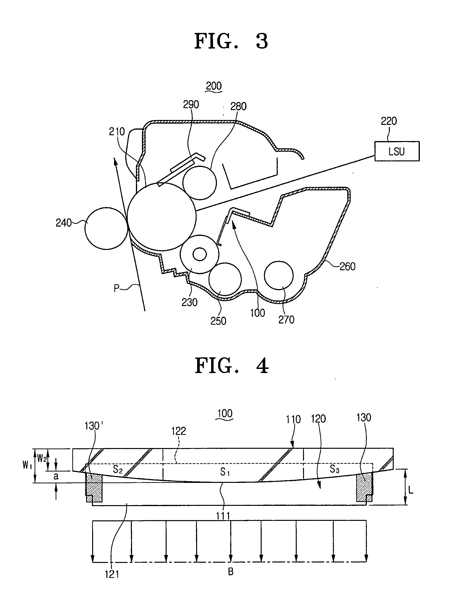
[0030]FIG. 3 is a schematic view depicting a development unit having a doctor blade according to an embodiment of the present invention, and FIG. 4 shows a contact pressure distribution between an elastic blade an...


PUM


Abstract

A doctor blade and a development unit having the same are disclosed. The doctor blade includes: an elastic blade having one edge contacting a developer roller with a predetermined pressure to control a toner layer formed on the developer roller; and a supporting member supporting the other edge portion of the elastic blade, wherein a middle portion of the supporting member is larger than each end portion of the supporting member. Accordingly, contact pressure between the elastic blade and the developer roller is uniformly distributed along a length direction of the elastic blade.

Description

CROSS-REFERENCE TO RELATED APPLICATIONS [0001] This application claims the benefit of Korean Patent Application No. 2005-43038, filed May 23, 2005, in the Korean Intellectual Property Office, the disclosure of which is incorporated herein by reference. BACKGROUND OF THE INVENTION [0002] 1. Field of the Invention [0003] Aspects of the present invention relate to a doctor blade and a development unit using the same in an electro-photographic type image forming apparatus such as a printer, a copier or a facsimile. [0004] 2. Description of the Related Art [0005] An electro-photographic type image forming apparatus forms an image on a print medium, such as a paper, when a signal such as a video signal is received from a host, such as a computer. In order to form the image on the print medium, the electro-photographic type image forming apparatus irradiates a laser beam on a photoconductor according to the video signal to form an electrostatic latent image on the photoconductor. The elect...

Claims


Application Information

Patent Timeline
IPC IPC(8): G03G15/08
CPCG03G2215/0866G03G15/0812G03G15/06G03G15/0822G03G2215/0634
Inventor KIM, YOUNG-MINNOH, JOO-HWAN
Owner SAMSUNG ELECTRONICS CO LTD
Learn More