Inkjet printing apparatus for applying uniform pressure on an applying roller

a printing apparatus and uniform pressure technology, applied in the direction of liquid/solution decomposition chemical coating, superimposed coating process, instruments, etc., can solve the problems of insufficient contact relationship between the liquid holding member and the printing roller, disadvantageous displacement of the application beads at the application start or end position of each applying medium, and inability to maintain uniform contact pressur

Inactive Publication Date: 2014-07-29
CANON KK
View PDF23 Cites 6 Cited by
  • Summary
  • Abstract
  • Description
  • Claims
  • Application Information

AI Technical Summary

Benefits of technology

[0012]An object of the present invention is to provide a liquid applying apparatus and an ink jet printing apparatus which enable a liquid holding member to contact with an applying roller under a uniform pressure. Another object of the present invention is to provide an applying mechanism which, while the applying roller rotates to perform an applying operation, allows a liquid to spread evenly on the applying roller and also allows the liquid on the applying roller to be appropriately collected in the liquid holding member.
[0017]In particular, the above-described construction includes the support means for holding the liquid holding member biased by the bias means so that the liquid holding member is pivotally movable by means of the pivotal axis. Thus, even if, for example, the direction of biasing to the applying roller deviates or the positional relationship between the liquid holding member and the applying roller deviates slightly, the liquid holding member can move depending on the deviation. More specifically, even if such a deviation as described occurs, the liquid holding member moves in the bias direction and pivots depending on the deviation. Thus, the contacting pressure of a contacting portion of the liquid holding member on the applying roller can be made uniform. As a result, the liquid can be stably and evenly applied.
[0018]Furthermore, according to the preferred aspect of the invention, the axis of the pivotal shaft of the support means is positioned inside the quadrangle formed by connecting the rotating center (P1) of the applying roller, the tangent point (P2) between the applying roller and the upstream side of the liquid holding member in the rotation of the applying roller, the tangent point (P3) between the applying roller and the downstream side of the liquid holding member in the rotation of the applying roller, and the intersecting point (P4) between the tangent line of the applying roller passing through the upstream tangent point (P2) and the tangent line of the applying roller passing through the downstream tangent point (P3). Thus, when the roller rotates, at the downstream tangent point (P3), where the applying roller contacts the contacting member of the liquid holding member, a frictional force (Ff3) is exerted in a tangential direction of the applying roller and acts on the liquid holding member. This frictional force can be decomposed into a component force (Fn3) acting in the direction of a line connecting a pivotal shaft axis (2013C) and the tangent point (P3) and a component force (Ft3) acting in a direction perpendicular to the component force (Fn3). In this case, the component force (Fn3) passing through the fitting shaft axis (2013C) is canceled out by a reaction force provided by the pivotal shaft (2013) of the support member. Consequently, behavior of the liquid holding member depends on another component force (Ft3). Here, if the axis (2013C) of the pivotal shaft is in the above-described positional relationship, the component force (Ft3) acts in a direction in which the liquid holding member is tightly contacted with the applying roller. As a result, at the downstream contact point of the contacting member, the pressure contact force between the applying roller and the contacting member is stably increased to allow the liquid to be adhered in an even and thin film form. On the other hand, on the upstream side, based on the same principle and in contrast, the pressure contact force between the liquid holding member and the applying roller is reduced to allow the liquid to be more easily collected. As a result, when the applying roller rotates to perform the applying operation, the liquid spreads evenly on the applying roller. Furthermore, the liquid on the applying roller can be appropriately collected in the liquid holding member.

Problems solved by technology

Thus, for example, if applying media of a relatively small size are intermittently conveyed and then applied, applying beads may disadvantageously be displaced at an applying start or end position for each applying medium.
However, in such a conventional liquid applying mechanism as described in Japanese Patent Laid-Open No. 2005-254229, the contacting relationship between the liquid holding member and the applying roller may be insufficient.
More specifically, with the conventional configuration, which maintains the contacting relationship simply by the biasing with the spring, a uniform contacting pressure cannot be maintained unless a relatively accurate positional relationship is established between the liquid holding member and the applying roller.
If the uniform contacting pressure fails to be maintained, the applying liquid may leak from the liquid holding member.
Thus, realizing the above-described behavior of the applying liquid by means of the applying mechanism is difficult.
However, even a slight deviation in the bias direction of the spring hinders prevention of the contacting portion of the liquid holding member from contacting unevenly against the applying roller, as shown by a dashed line in FIG. 11.
In this case, when the liquid holding member moving in conjunction with the applying roller is stopped, the applying liquid may leak from the liquid holding space.

Method used


Image

  • Inkjet printing apparatus for applying uniform pressure on an applying roller
  • Inkjet printing apparatus for applying uniform pressure on an applying roller
  • Inkjet printing apparatus for applying uniform pressure on an applying roller

Examples


Embodiment Construction

[0031]An embodiment of the present invention will be described below with reference to the drawings.

[0032]The embodiment of the present invention relates to a hybrid machine composed of a document reading device and a printing apparatus based on an ink jet scheme. In particular, the embodiment relates to an ink jet printing apparatus including a liquid applying mechanism which, when a print medium is printed with ink composed of a pigment as a color material, applies the print medium with a liquid for a predetermined purpose such as promotion of cohesion of the pigment.

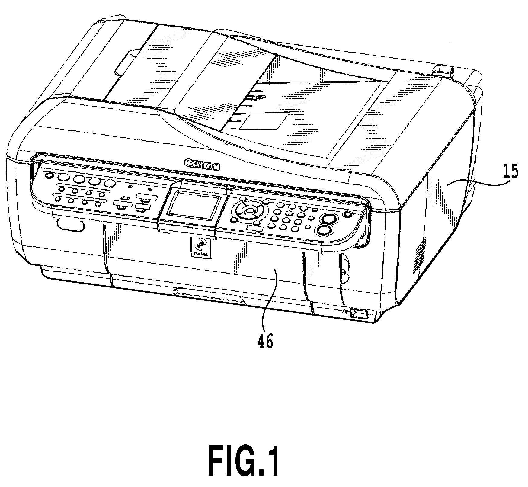
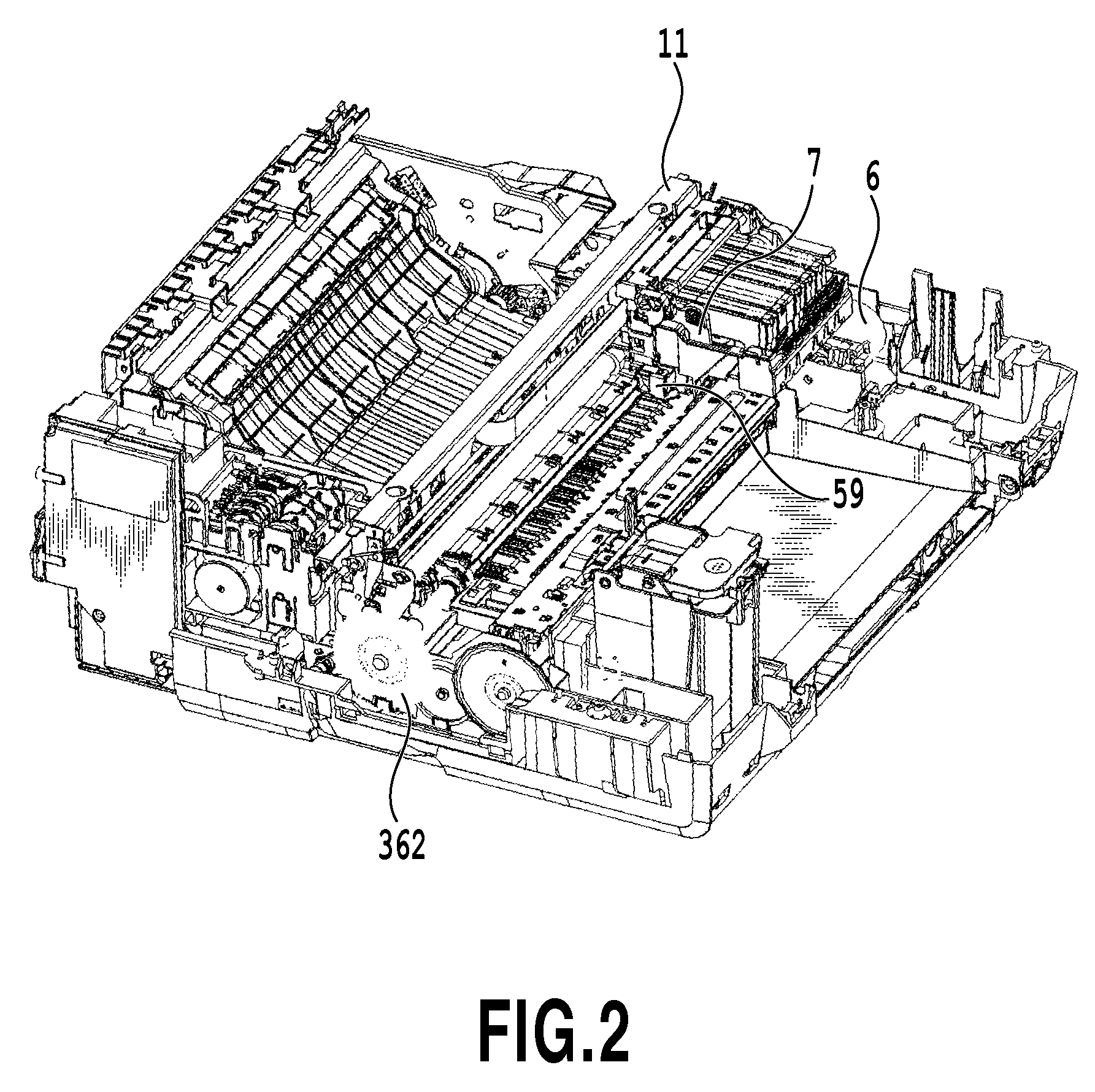
[0033]FIG. 1 is a perspective view showing an appearance of the above-described hybrid machine. FIGS. 2 and 3 are perspective views of the hybrid machine shown in FIG. 1 and from which an outer case has been removed, the perspective views showing an internal configuration of the printing apparatus as viewed from front left and front right, respectively. FIG. 4 is a vertical sectional view also showing the internal con...


PUM

PropertyMeasurementUnit
sizeaaaaaaaaaa
surface roughnessaaaaaaaaaa

Abstract

A cap sheet metal (and pivot sheet metal) is configured to be able to move linearly with a cap arm (and an arm stay) via engagement between an engagement hole and a fitting shaft. Furthermore, the cap sheet metal (and the pivot sheet metal) can move pivotally with respect to the cap arm (and the arm stay) using the fitting shaft, which engages with the engagement hole, as a pivotal shaft. Thus, even if, for example, the direction of biasing toward the applying roller deviates or a positional relationship with the applying roller deviates slightly, the liquid holding member moves and pivots in the bias direction depending on the deviation. As a result, the contacting pressure of a contacting portion on the applying roller can be made uniform.

Description

BACKGROUND OF THE INVENTION[0001]1. Field of the Invention[0002]The present invention relates to a liquid applying apparatus and an ink jet printing apparatus, and specifically to a liquid applying apparatus that applies a liquid on a medium such as a print sheet for a predetermined purpose, for example, coagulation of an ink color material, and an ink jet printing apparatus including the liquid applying apparatus.[0003]2. Description of the Related Art[0004]Spin coaters, roll coaters, bar coaters, and die coaters are widely known as methods of applying a liquid or a liquid material on media. These applying methods are based on consecutive applying on relatively elongate applying media. Thus, for example, if applying media of a relatively small size are intermittently conveyed and then applied, applying beads may disadvantageously be displaced at an applying start or end position for each applying medium. Thus, for example, resulting coated films may be prevented from being uniform....

Claims


Application Information

Patent Timeline
Patent Type & Authority Patents(United States)
IPC IPC(8): B05C1/06B05C1/00B05C1/08B05D1/28B41F31/00G03G15/01
CPCB05C1/0869B05C1/0834G03G2215/2058B41J11/0015
Inventor NAGAHARA, HIDEAKIOHASHI, TETSUYOYOSHINO, HIROSHISEKINO, TAKESHIHAKAMATA, KEISEI
Owner CANON KK
Why Eureka
Try Eureka