Gripper

Inactive Publication Date: 2014-08-21
ZOPPI MATTEO +3
View PDF11 Cites 6 Cited by
  • Summary
  • Abstract
  • Description
  • Claims
  • Application Information

AI Technical Summary

Benefits of technology

[0052]Since the gripping means are preferably made of metal or other elastic material, this folding gives compliance to the gripping means. With t

Problems solved by technology

The displacement, in this case, can be adjusted on the base of the length of the fingers but the parts of the fingers in contact with the grasped body do not u

Method used


Image

  • Gripper
  • Gripper
  • Gripper

Examples


Example

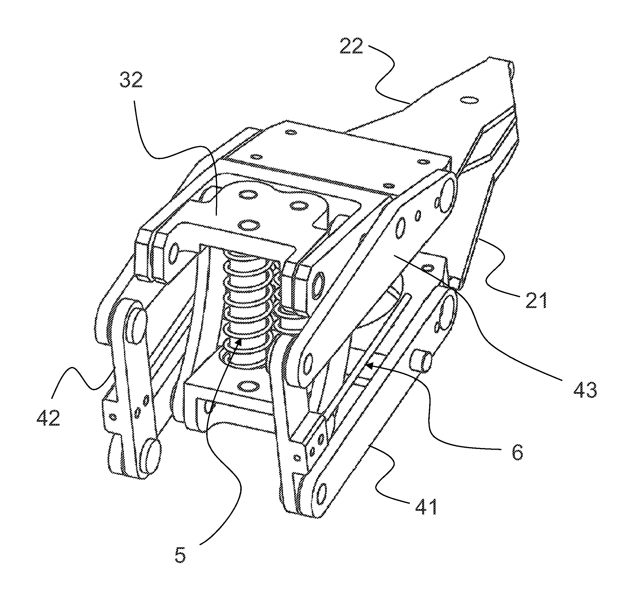
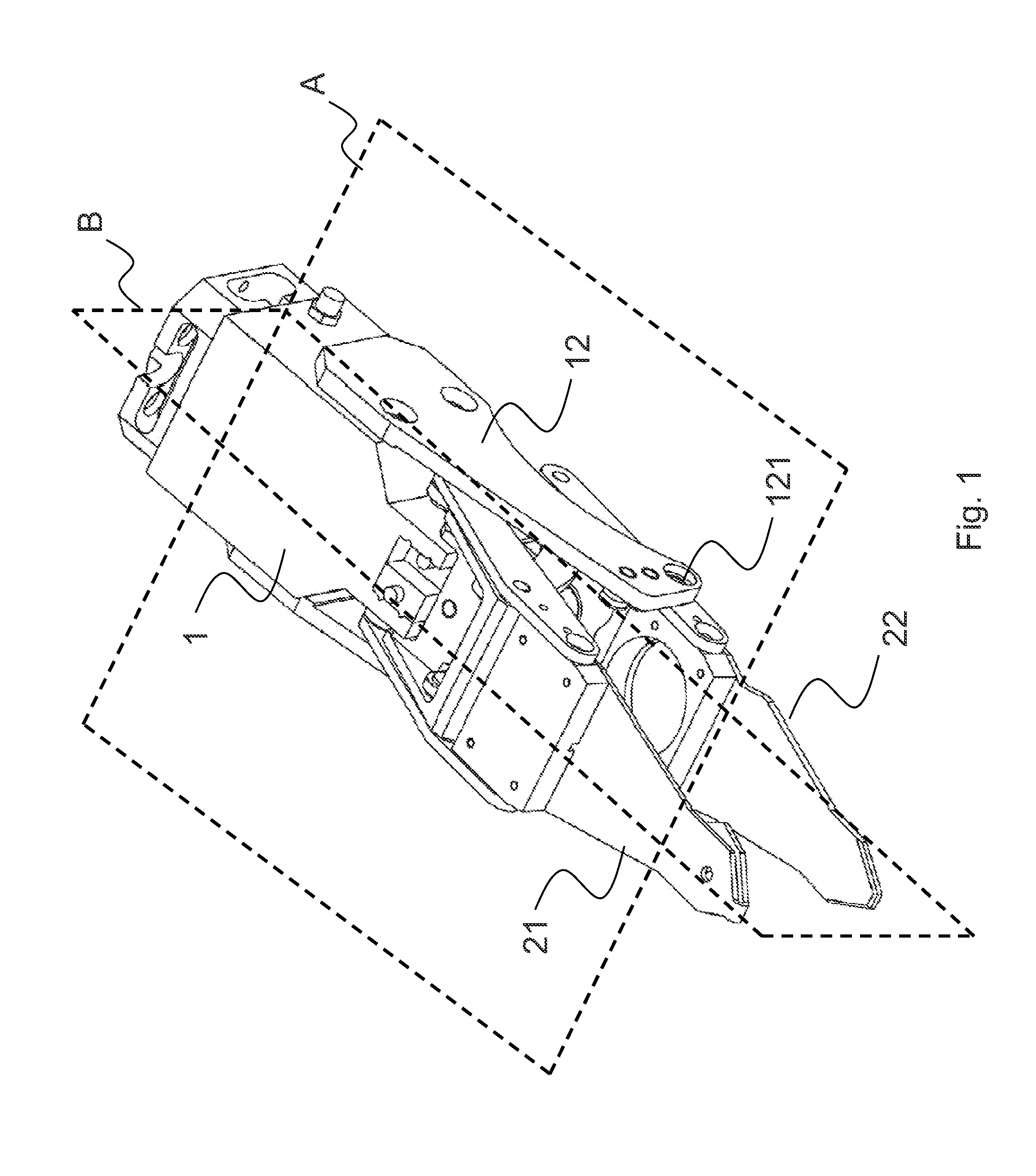
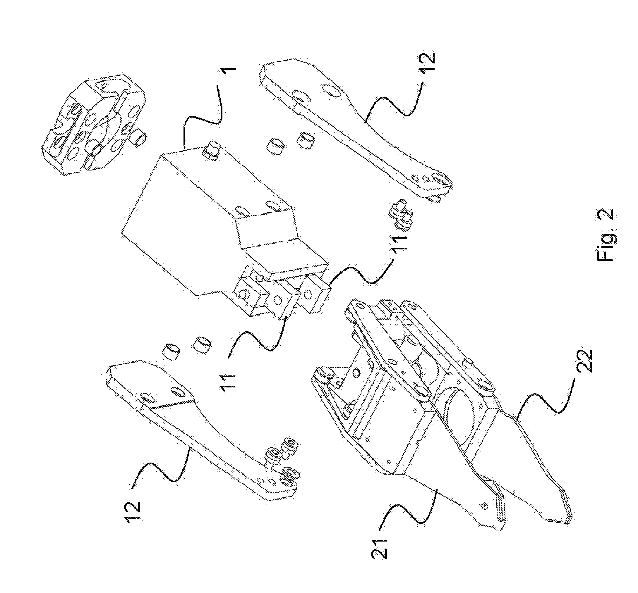
[0062]The below described pictures relate to a preferred embodiment of a gripper according to the present invention. They are shown with the aim to clarify and not limit the scope and breadth of the invention, which covers the realization of a gripper for manipulating objects with irregular or deformable geometry, with the advantageous characteristics that were described previously.

[0063]With reference to the figures, a gripper according to the present invention comprises an external body 1, in which at least one driving unit is present. This driving unit moves at least two sliding elements 11 according to a motion of translation, in such a way that the at least two sliding elements 11 move away from and approach each other symmetrically with respect to a longitudinal mid-plane A of the gripper, passing from a configuration of maximum mutual approach to a configuration of maximum mutual spacing.

[0064]The motion of the sliding elements 11 actuates the opening and closing of the gripp...


PUM


Abstract

A gripper for grasping and handling textiles and other flexible materials includes an external body housing a driving unit, which actuates a plurality of sliding elements moving away and approaching symmetrically; and a plurality of gripping members, each connected to one of the sliding elements by a first transmission group that includes a kinematic chain with levers that invert motion such that, during the approaching of the sliding elements, the gripping members move away from each other, and during the distancing of the sliding elements, the gripping members approach each other.

Description

FIELD OF THE INVENTION[0001]The present invention relates to a gripper having an external body, in which a driving unit is housed. This driving unit actuates a plurality of sliding elements according to a translational motion, such that the sliding elements move away from and approach each other in a symmetric manner with respect to a longitudinal mid-plane of the gripper, passing from a maximum mutual approach condition to a maximum mutual spacing condition. A plurality of gripping members are also included, each connected to one of the sliding elements.BACKGROUND OF THE INVENTION[0002]In general terms, the above described architecture described is a common architecture of industrial grippers according to the state of the art.[0003]Different types of industrial grippers exist and can be classified mainly based on two characteristics: the displacements of the rotary or sliding fingers of the gripper, and the force that the fingers apply to the grasped body.[0004]Following the above ...

Claims


Application Information

Patent Timeline
IPC IPC(8): B25J15/00
CPCB25J15/0028B25J15/0206D06F89/00D06F95/00
Inventor ZOPPI, MATTEOMOLFINO, REZIAJILICH, MICHALLE, THUY HONG LOAN
Owner ZOPPI MATTEO
Why Eureka
Try Eureka