Arrangement of electrical modules, converter and aircraft with such an arrangement, and method for producing the arrangement

a technology of electrical modules and arrangement, which is applied in the direction of electrical apparatus construction details, basic electric elements, sustainable transportation, etc., can solve the problems of increasing the total weight of the system, non-uniform current distribution, and non-uniform loading of power modules, so as to reduce the tensile force, simplify the clamping device, and reduce the effect of tensile for

Active Publication Date: 2021-07-15
ROLLS ROYCE DEUT LTD & CO KG
View PDF0 Cites 7 Cited by
  • Summary
  • Abstract
  • Description
  • Claims
  • Application Information

AI Technical Summary

Benefits of technology

[0015]By way of suitable arrangement of the leadthroughs and the course of the clamping element, pulley blocks may be implemented in order to minimize the tensile force that has to be applied.
[0016]The present embodiments provide the following advantages: homogeneous introduction of force and therefore uniform contact pressure on electrical components; saving of a heavy clamping frame (e.g., providing lightweight construction); simplification of the clamping devices for curved contact surfaces or free-form surfaces; saving of screw points and therefore of construction volume; saving of pressure compensation materials; and a clamping system that may be used in a flexible manner.
[0021]In one development, the clamping element may be wound a plurality of times around the first deflection elements and the second deflection elements such that a pulley block is formed. As a result, higher contact pressures may be generated.

Problems solved by technology

This increases a total weight of the system.
This results in non-uniform distribution of current and, therefore, non-uniform loading on the power modules.
This reduces the overall efficiency and reduces the service life of an overall system (e.g., of a converter).
However, different distances between the power modules and the screw connection points of the clamping frame result in different resulting forces on the power modules.
Uniform distribution of forces may only be achieved with a high level of complexity in terms of design, where 100% uniform pressing on the individual power modules cannot be guaranteed by known clamping frame concepts.
In summary, the following problems arise: high costs and high level of technical complexity; oversizing due to identical power modules being connected in parallel; a higher weight due to the high level of complexity in terms of design; and a larger volume (e.g., installation space).

Method used


Image

  • Arrangement of electrical modules, converter and aircraft with such an arrangement, and method for producing the arrangement
  • Arrangement of electrical modules, converter and aircraft with such an arrangement, and method for producing the arrangement

Examples


Embodiment Construction

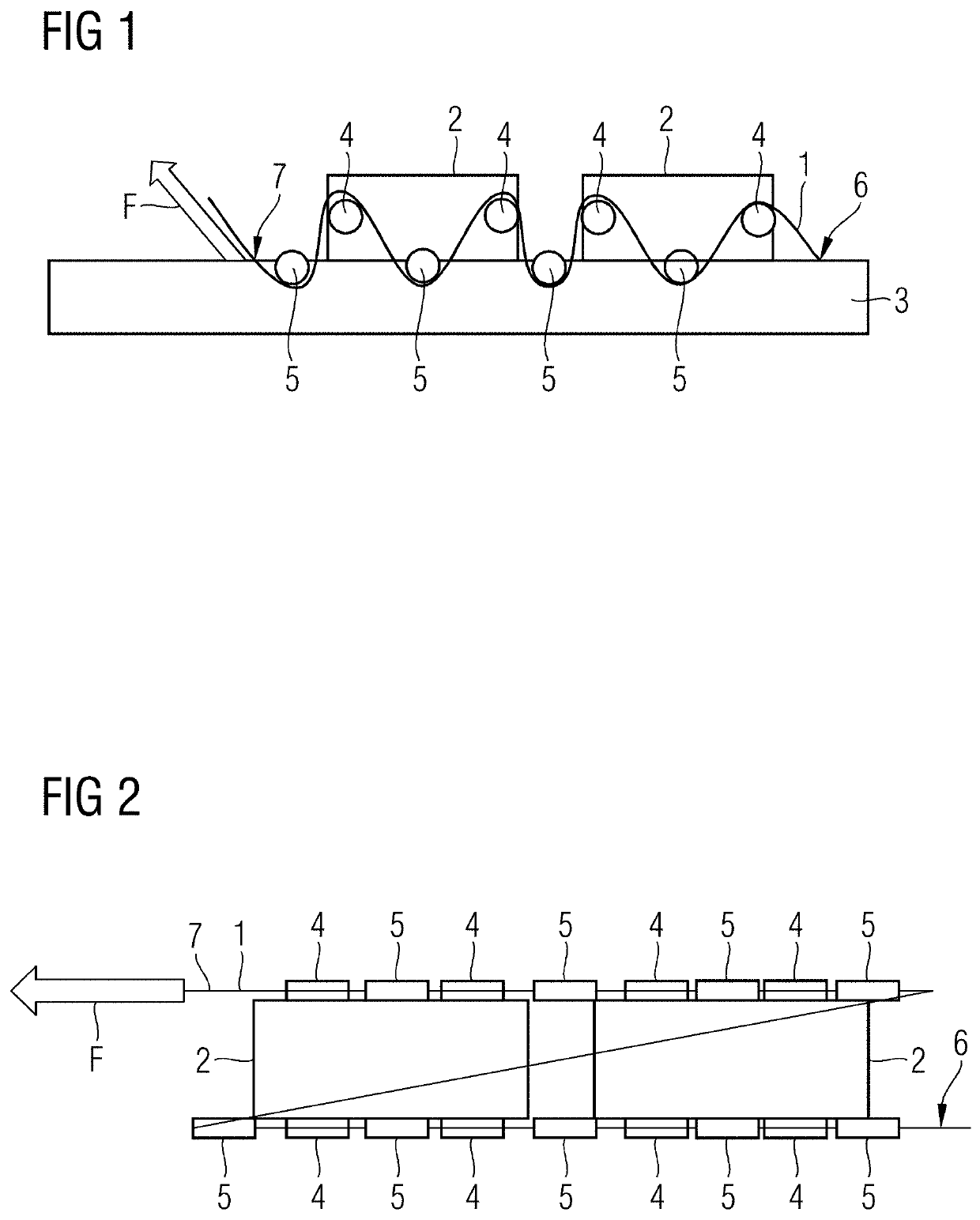
[0031]FIG. 1 shows a side view of one embodiment of an arrangement including a rope-like clamping element 1. Electrical modules 2 are arranged on a heat sink 3. Electrical modules 2 may be, for example, individual electrical / electronic components or entire electrical assemblies.

[0032]The electrical modules 2 have first deflection elements 4 that are arranged or formed laterally. With the aid of the first deflection elements 4, the clamping element 1 may be deflected. In this case, the electrical module 2 is pressed with a force-fit perpendicularly onto a surface of the heat sink 3 when the clamping element 1 is under tension. The second deflection elements 5, which are formed on or in the heat sink 3, serve as mating elements for the first deflection elements 4 and for clamping purposes.

[0033]The first deflection elements 4 and the second deflection elements 5 are spatially offset in relation to one another, so that the clamping element 1, which is under tension, presses the electri...


PUM


Abstract

The invention specifies an arrangement having at least one electrical module (2) which is arranged on a heat sink (3). The arrangement has:—first deflection elements (4) which are formed in or on the electrical module (2),—second deflection elements which are formed in or on the heat sink (3), and—at least one flexible, cable- or strip-like tensioning element (1),—which is arranged between the first and second deflection elements (4, 5) under tension (F) in such a way that the electrical module (2) is pressed onto the heat sink (3). A converter and an aircraft having an arrangement of this kind and also a method for producing an arrangement of this kind are likewise specified.

Description

[0001]This application is the National Stage of International Application No. PCT / EP2019 / 060489, filed Apr. 24, 2019, which claims the benefit of German Patent Application No. DE 10 2018 207 033.3, filed May 7, 2018. The entire contents of these documents are hereby incorporated herein by reference.FIELD[0002]The present embodiments relate to an arrangement including an electrical module that is arranged on a heat sink, a power converter including such an arrangement, and an aircraft to the power converter. The present embodiments also relate to a method for producing an arrangement of this kind.BACKGROUND[0003]Power modules (e.g., modules with power semiconductors) for, for example, power converters or other electrical modules that are subject to power loss are often pressed onto heat sinks. Thermally conductive pastes or thermally conductive foils are used to compensate for the deformation, sagging, or roughness between the two contact partners (e.g., heat sink and power module).[...

Claims


Application Information

Patent Timeline
Patent Type & Authority Applications(United States)
IPC IPC(8): H05K7/20B64D33/10B64D27/24H01L23/40
CPCH05K7/2049H05K7/20909H05K7/20454B64D2027/026B64D27/24H01L23/40B64D33/10H01L23/367H05K7/209Y02T50/60Y02T50/40
Inventor WALTRICH, UWE
Owner ROLLS ROYCE DEUT LTD & CO KG
Why Eureka
Try Eureka