
Balanced, multi-stud hold-down

a multi-stud, balanced technology, applied in the direction of girders, instruments, data processing applications, etc., can solve the problems of building toms, structural failure, subject walls and other elements of buildings to tremendous forces, and achieve the effect of convenient and quick securemen

Inactive Publication Date: 2006-11-23
COMMINS ALFRED D
View PDF35 Cites 24 Cited by
  • Summary
  • Abstract
  • Description
  • Claims
  • Application Information

AI Technical Summary

Benefits of technology

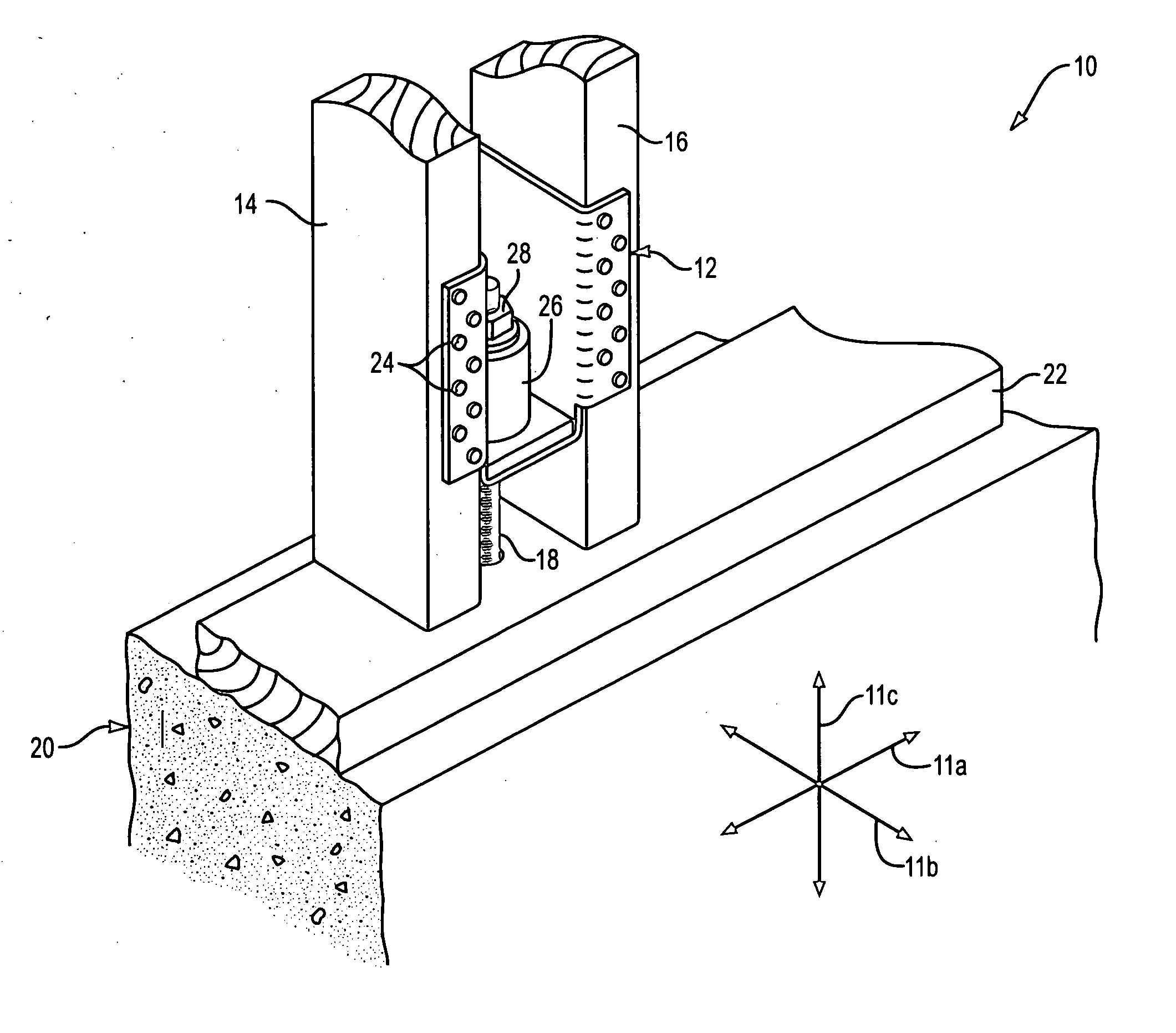
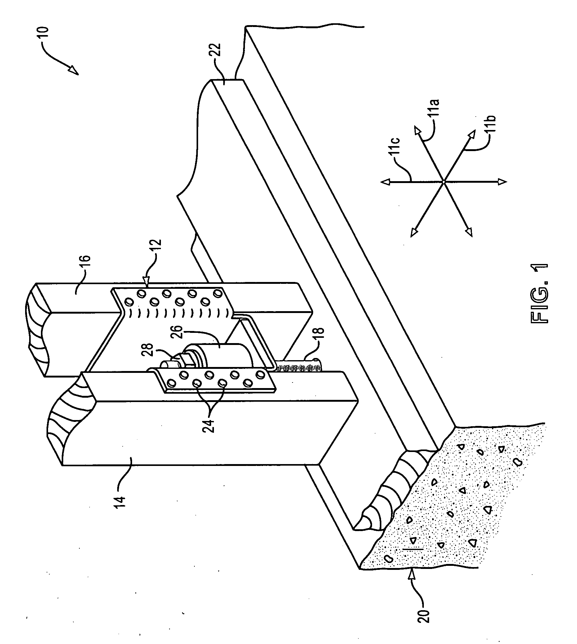
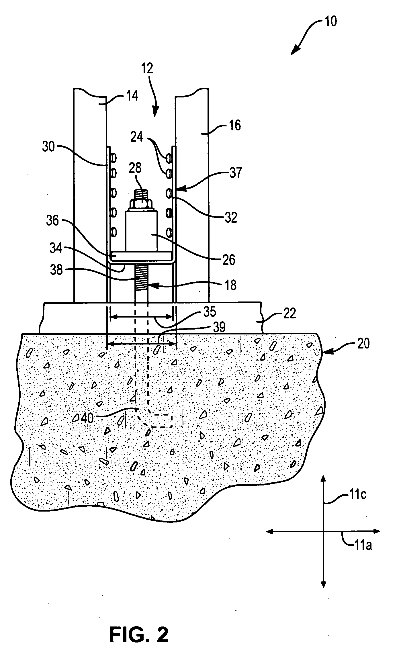
"The present invention provides a balanced hold-down that can be easily and quickly secured to support members in a balanced manner. The hold-down can be mass produced inexpensively and can be installed from a location that is not collinear with the support members. The securement mechanisms can be introduced through securement apertures of the flanges at any suitable angle with respect to the surface to which they are being secured. The hold-down can be used with both rectangular and non-rectangular support members. The base of the hold-down can be designed to resist distortion or failure during installation and the subsequent loading that may be experienced during strong winds, earthquakes, and the like. The securement mechanisms can be introduced through securement apertures of the flanges at any suitable angle with respect to the surface to which they are being secured. The invention provides a simple and effective solution for securing support members in a balanced manner."

Problems solved by technology

Strong winds and earthquakes subject walls and others elements of a building to tremendous forces.
If these forces are not distributed to the proper elements or structures capable of withstanding such force, the building may be tom apart.
Securement promotes single body motion and limits whiplash amplification that often results in structural failure.
Tall narrow shear walls, which may be found in nearly all homes, act as lever arms and may magnify an imposed load.
Eccentric attachment may also cause the support member to deflect excessively.
Bowing tends to promote column buckling and reduces the effectiveness of the support member to provide sufficient structural support.
Moreover, hold-downs are difficult to install and expensive to fabricate.

Method used


Image

  • Balanced, multi-stud hold-down
  • Balanced, multi-stud hold-down
  • Balanced, multi-stud hold-down

Examples


Embodiment Construction

[0041] It will be readily understood that the components of the present invention, as generally described and illustrated in the Figures herein, may be arranged and designed in a wide variety of different configurations. Thus, the following more detailed description of the embodiments of the system and method of the present invention, as represented in FIGS. 1 through 17, is not intended to limit the scope of the invention. Several Figures display an automatic take-up device. This device is described fully in U.S. Patent Application Ser. No. 60 / 156,042 previously filed by this inventor, and incorporated herein by reference.

[0042] Those of ordinary skill in the art will, of course, appreciate that various modifications to the details of the Figures may easily be made without departing from the essential characteristics of the invention. Thus, the following description of the Figures is intended only by way of example, and simply illustrates certain embodiments consistent with the in...


PUM


Abstract

A hold-down for securing first and second support members in a portion of a building to an anchoring device extending from another portion of the building. The hold-down may include a first flange having securement apertures therethrough configured to receive fasteners adapted to secure the first flange to the first support member. A second flange may have securement apertures configured to receive fasteners adapted to secure the second flange to the second support member. A base may connect the first and second flanges and have an aperture sized and positioned to receive the anchoring device therethrough. The first and second flanges may be configured to be loaded substantially exclusively in tension by the anchoring device.

Description

RELATED APPLICATIONS [0001] This application is a continuation of U.S. patent application Ser. No. 10 / 673,592 filed Sep. 29, 2003, entitled “BALANCED, MULTI-STUD HOLD-DOWN,” which will issue Mar. 7, 2006 as U.S. Pat. No. 7,007,432, which is a continuation of U.S. Pat. No. 6,625,945, which claims priority to U.S. Provisional Application Ser. No. 60 / 223,758, filed on Aug. 8, 2000 and entitled “MULTI-STUD CONCENTRIC HOLD-DOWN.”BACKGROUND [0002] 1. Field of the Invention [0003] The present invention relates to building construction, and more specifically, to apparatus for anchoring walls to foundations and lower floors. [0004] 2. Background [0005] Strong winds and earthquakes subject walls and others elements of a building to tremendous forces. If these forces are not distributed to the proper elements or structures capable of withstanding such force, the building may be tom apart. Foundations are often the strongest element of a building. Securely tying the walls of a building to the f...

Claims


Application Information

Patent Timeline
Patent Type & Authority Applications(United States)
IPC IPC(8): G07G1/00E04B1/00E04B1/26E04B5/12E04C3/12
CPCE04B1/2604E04B1/2608E04B5/12Y10T403/5781E04B2001/2684E04C3/12G06Q10/063E04B2001/2463
Inventor COMMINS, ALFRED D.
Owner COMMINS ALFRED D
Learn More