Rotary cutter and method for adjusting fixing angle of stationary blade in rotary cutter

Inactive Publication Date: 2006-11-30
KOYO JIDOKI
View PDF14 Cites 14 Cited by
  • Summary
  • Abstract
  • Description
  • Claims
  • Application Information

AI Technical Summary

Benefits of technology

[0029] As a consequence, the cutting operation can be interrupted by forcibly oscillating the oscillating member while the cutter drum is continuously rotated, and further, the cutting operation can be performed only by returning the oscillating member to an original position, thereby almost eliminating a waiting time and remarkably enhancing cutting efficiency.
[0030] (3) The versatile motor can be used as the drive source for the cutter drum, thereby obviating a conventional servo motor and a program for controlling the servo motor, so as to reduce the cost of the rotary c

Problems solved by technology

However, the above-described rotary cutter in the prior art has had problems to be solved, as follows:
In particular, in the rotary cutter installed in the labeling machine, a cutting work is forced at a high speed with respect to 400 to 700 pieces of extra thin roll label sheets per minute, and therefore, the adjustment accuracy of both of the blades 12 and 21 markedly influences on a cutting level

Method used


Image

  • Rotary cutter and method for adjusting fixing angle of stationary blade in rotary cutter
  • Rotary cutter and method for adjusting fixing angle of stationary blade in rotary cutter
  • Rotary cutter and method for adjusting fixing angle of stationary blade in rotary cutter

Examples


Example

[0041] A description will be given below of preferred embodiments according to the invention in reference to the attached drawings.

(1) Outline of Rotary Cutter

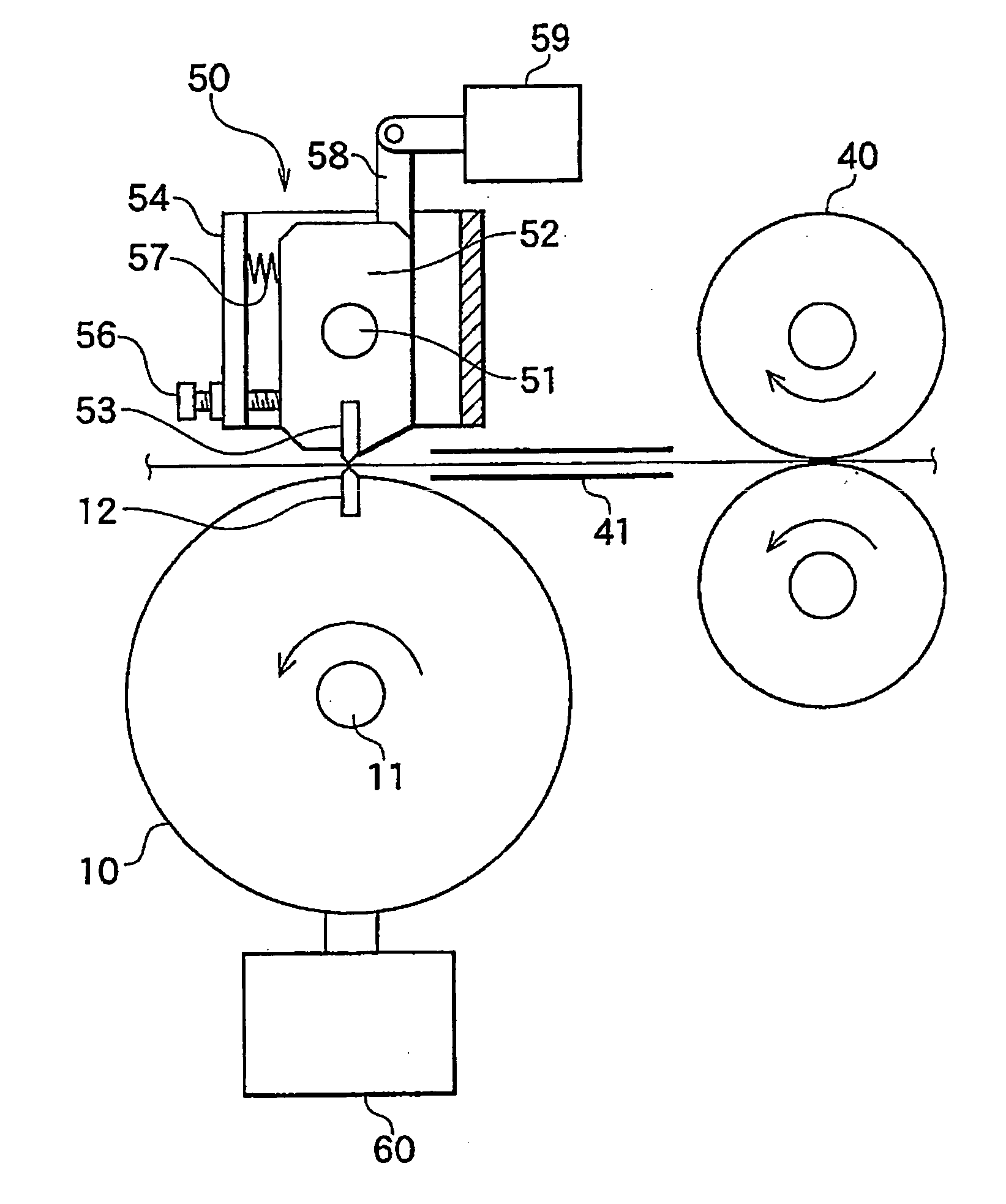
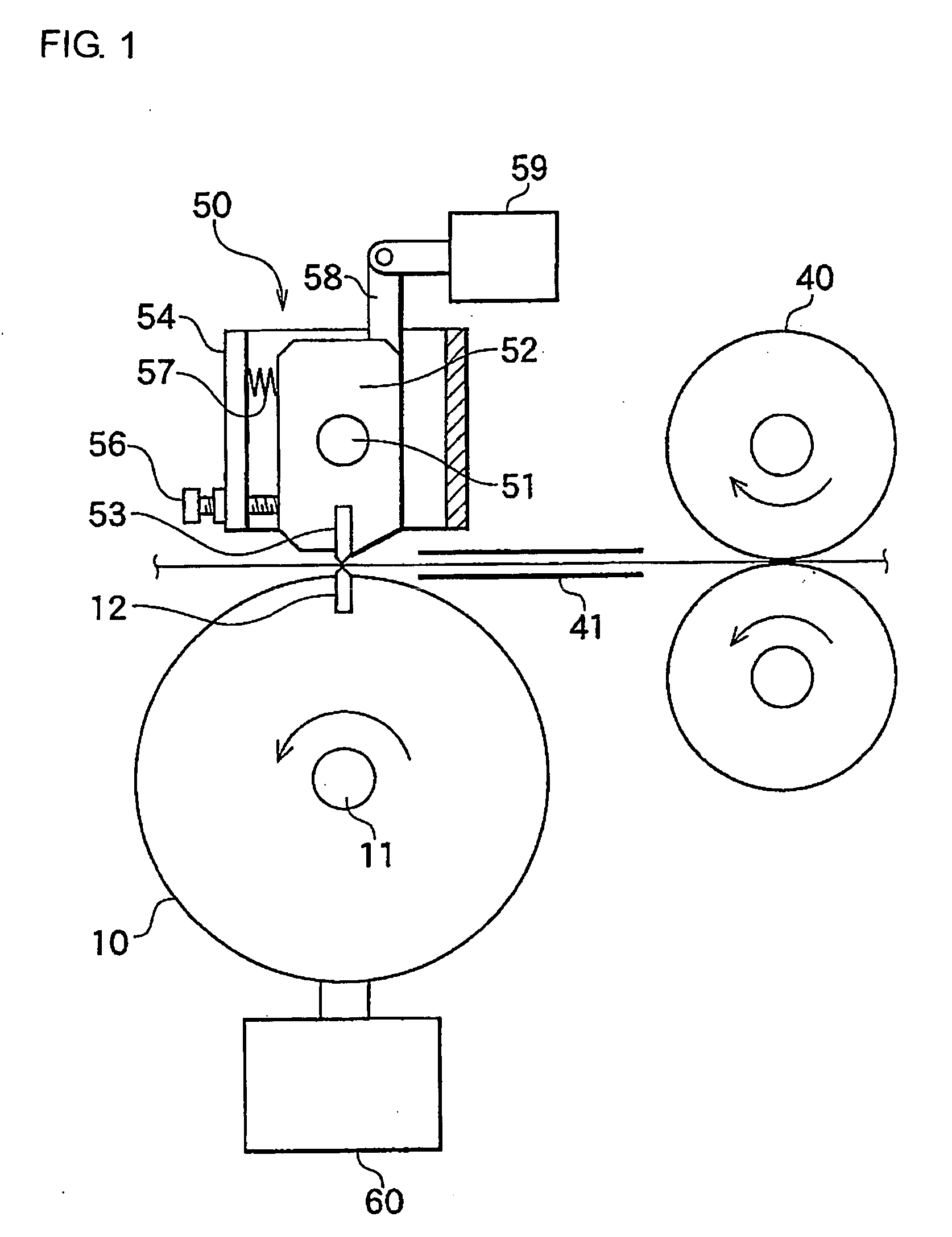
[0042]FIG. 1 is a view showing a model of a rotary cutter.

[0043] A supply roller 40 consisting of a pair of rollers is located on the right in FIG. 1. Moreover, a guide plate 41 for introducing a roll label is positioned in front of the supply roller 40. A rotary cutter is installed on the left of the guide plate 41.

[0044] No servo motor is used as a drive source for the supply roller 40. A gear mechanism can satisfactorily serve as a drive source for the supply roller 40.

[0045] The rotary cutter comprises a cutter drum 10, which is rotated in one direction on a strut 11, and a stationary cutter 50 disposed in a manner facing to the cutter drum 10, like in the prior art. However, the invention is different from the prior art in that no servo motor is used as the drive sources for the cutter drum 10 and the supply roller 4...


PUM

PropertyMeasurementUnit
Angleaaaaaaaaaa

Abstract

A rotary cutter is configured such that a stationary cutter includes: an oscillating member oscillatably pivoted on a strut; a stationary blade projecting on one side of the oscillating member; oscillation restricting means for restricting oscillation of the oscillating member in one direction; a resilient member for applying an urging force to the oscillating member at all times in a direction in which the oscillation is restricted; and oscillating means for forcibly applying an oscillating force to the oscillating member; wherein the oscillating member is supported at three points, that is, a contact point between the resilient member and the oscillating member, a contact point between the oscillation restricting means and the oscillating member, and a pivotal point of the strut of the oscillating member. Thus, it is possible to adjust a fixing angle of the stationary blade at a proper angle by a simple operation and reduce the cost of the rotary cutter.

Description

BACKGROUND OF THE INVENTION [0001] 1. Field of the Invention [0002] The invention relates to a rotary cutter applicable to a labeling machine or a printer and, more particularly, to a rotary cutter for continuously cutting a tape-like sheet in a precise length and a method for adjusting a fixing angle of a stationary blade in the rotary cutter. [0003] 2. Description of the Related Art [0004]FIG. 7 is a view showing a model of a rotary cutter installed in a labeling machine. [0005] A conventional rotary cutter comprises a cutter drum 10, which is rotated in one direction on a strut 11, and a stationary cutter 20 arranged in a manner facing to the cutter drum 10. [0006] A stationary blade 21 projects from the stationary cutter 20. A facing distance between a blade tip of the stationary blade 21 and a rotary blade 12 disposed at the cutter drum 10 can be designed to be manually adjusted. [0007] The cutter drum 10 includes the rotary blade 12 projecting from the outer peripheral surface...

Claims


Application Information

Patent Timeline
IPC IPC(8): B26D7/06
CPCB26D7/2628B26D1/385Y10T83/2137
Inventor YAMASHITA, KYOICHI
Owner KOYO JIDOKI
Why Eureka
Try Eureka