Valve for the venting circuit of a liquid tank

a valve and liquid tank technology, applied in mechanical equipment, functional valve types, transportation and packaging, etc., can solve the problems of difficult parts, high manufacturing cost, and delay in opening of valves

Inactive Publication Date: 2006-11-30
INERGY AUTOMOTIVE SYST RES (SA)
View PDF33 Cites 17 Cited by
  • Summary
  • Abstract
  • Description
  • Claims
  • Application Information

AI Technical Summary

Benefits of technology

[0014] The valve according to the invention is preferably intended for the circuit for venting a tank, which may contain any liquid. In particular, the liquid may be a fuel, a brake...

Problems solved by technology

Such valves often have the drawback of a delay in opening, which is due to the fact that the force pressing the needle against the aperture (and due to the pressure difference on either sid...

Method used


Image

  • Valve for the venting circuit of a liquid tank
  • Valve for the venting circuit of a liquid tank
  • Valve for the venting circuit of a liquid tank

Examples


first embodiment

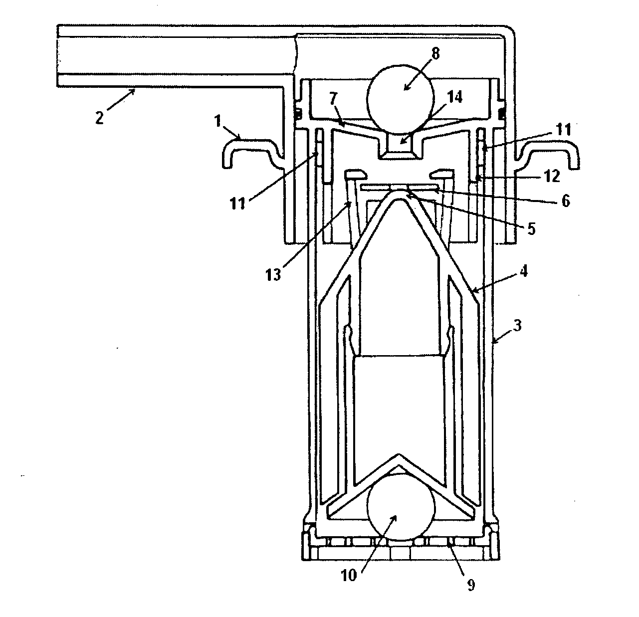
[0026] According to the invention, the needle has, at its upper end (or tip), a larger cross section than that of the aperture in the seal. Within the context of the invention, such a geometry means that the needle also has a cross section generally smaller than the cross section of the aperture in the seal. In this way, the seal can slide freely over a large portion of the needle, but is stopped in its travel by the tip. In this embodiment, the lower end of the needle (or its base for anchoring onto the head of the float) preferably has a cross section substantially equal (in shape and size) to that of the aperture of the seal so as to ensure perfect sealing in the closed position of the valve.

[0027] Consequently, a needle geometry that is very suitable for this embodiment is that in which the needle is essentially conical but is provided with a stop device at its tip. This stop device preferably has a conical lateral surface so as to make it easier to pass through the aperture of ...

second embodiment

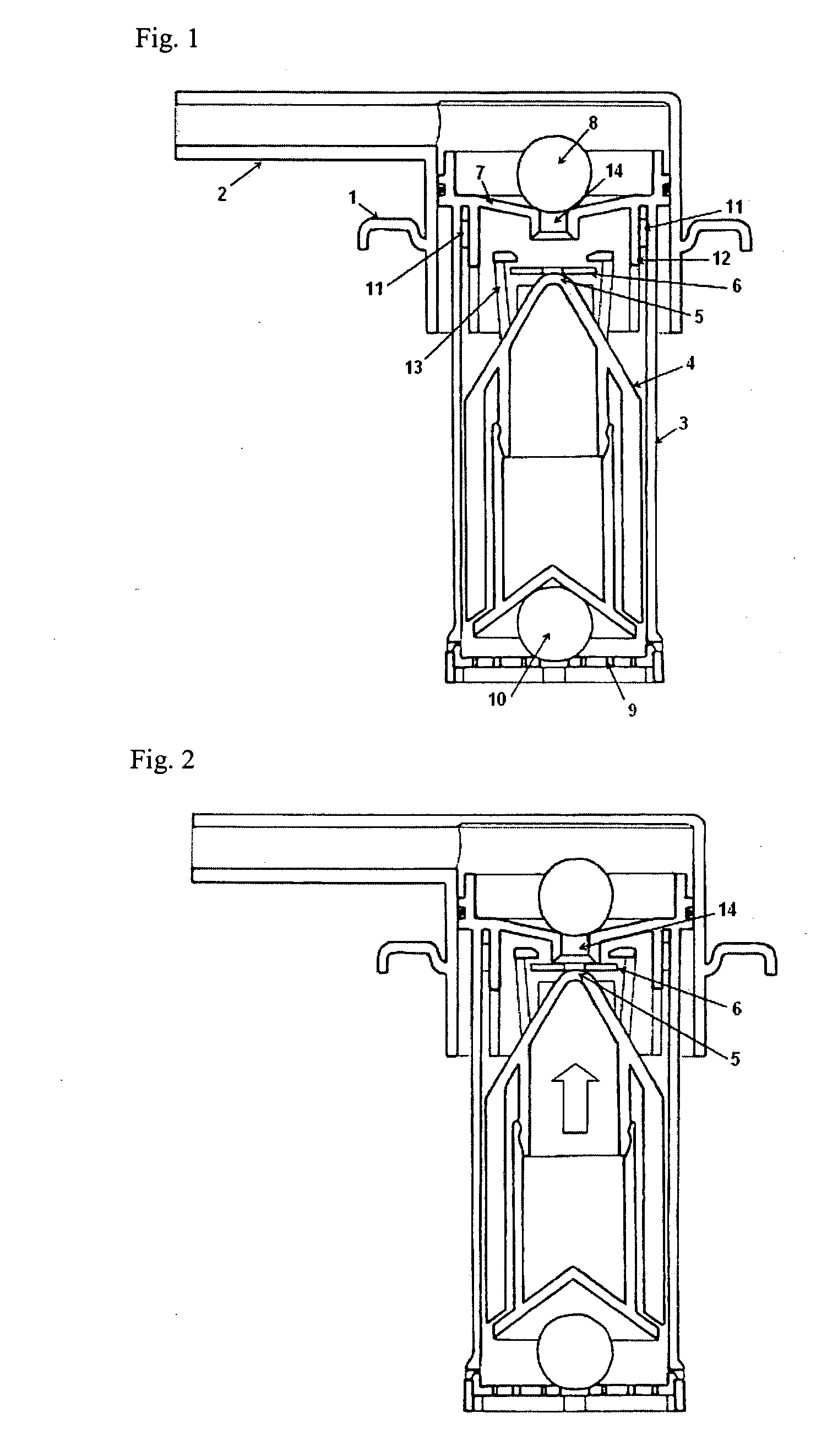
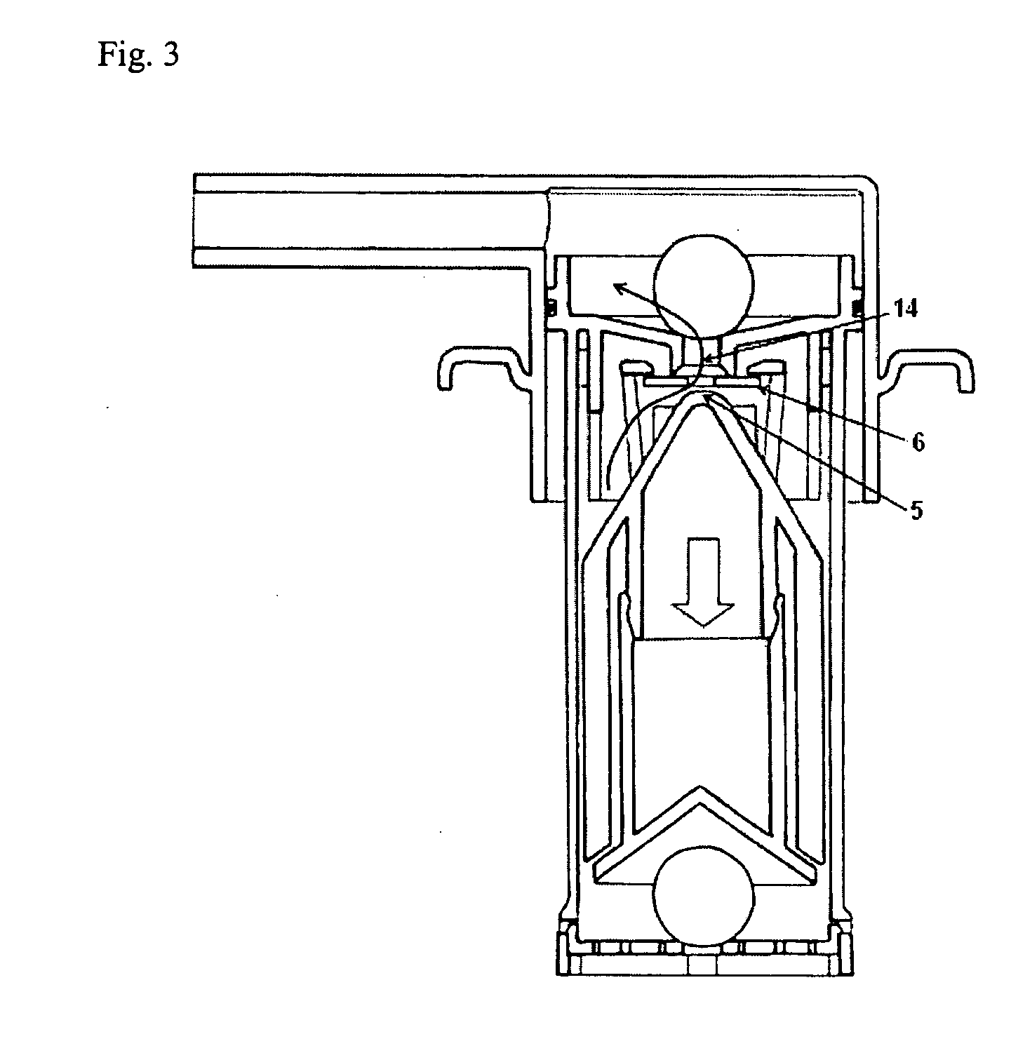
[0029] Thus, according to a preferred second embodiment of the invention, the head of the float comprises vertical hooked fingers that surround the needle and have an upper end higher than the needle. In this way, the seal can slide vertically between the hooked end of the fingers and a position where it bears on the head of the float. The term “hooked” is understood in fact to mean any shape allowing the seal to be retained. This shape may for example be that of an “L” on its tip.

[0030] In this embodiment, there are preferably at least three fingers so as to prevent the seal from leaking between two consecutive fingers. Most particularly preferably, there are at least four of them so as to limit this risk. These fingers are preferably placed symmetrically on the head of the float, and therefore in the form of a cross with equal branches when there are four of them. Most particularly preferably, these fingers guide the seal during its vertical travel, so as to minimize its lateral m...


PUM


Abstract

Valve for the venting circuit of a liquid tank, said valve containing:
    • a) a chamber (3) which opens into the tank and is connected via an aperture to the venting circuit; b) a float containing a head provided with a needle and able to slide vertically inside the chamber; and c) a closure member for closing off the venting aperture and itself having an aperture that can be closed off by the needle of the float, the closure member having a flexible seal which is capable of moving substantially vertically relative to the head of the float, said head being provided with a device for limiting the movement of the seal

Description

REFERENCE TO PRIOR APPLICATIONS [0001] This application claims priority to French patent application 0505195 filed May 24, 2005, incorporated herein by reference. FIELD OF THE INVENTION [0002] The present invention relates to a valve for the venting circuit of a liquid tank, in particular a fuel tank with which a motor vehicle may be equipped. [0003] Additional advantages and other features of the present invention will be set forth in part in the description that follows and in part will become apparent to those having ordinary skill in the art upon examination of the following or may be learned from the practice of the present invention. The advantages of the present invention may be realized and obtained as particularly pointed out in the appended claims. As will be realized, the present invention is capable of other and different embodiments, and its several details are capable of modifications in various obvious respects, all without departing from the present invention. The de...

Claims


Application Information

Patent Timeline
IPC IPC(8): F16K24/04
CPCB60K15/03519F16K24/042F16K17/36Y10T137/3099Y10T137/0874Y10T137/7358F16K24/04B60K15/035
Inventor GANACHAUD, PATRICKROUXEL, THIERRYCUVELIER, VINCENT
Owner INERGY AUTOMOTIVE SYST RES (SA)
Why Eureka
Try Eureka