Membrane electrode assembly comprising a catalyst migration barrier layer

a technology of migration barrier layer and membrane electrode, which is applied in the field of membrane electrode assembly, can solve the problems of affecting the entire cell and system, limiting the lifetime of the membrane electrode assembly (mea) of a fuel cell, and significant part of the cost allotted to the expensive pt-catalyst material, so as to improve the mechanical strength of the porous ionomer containing layer, improve the interface, and improve the tortuosity of the porous

Active Publication Date: 2011-10-20
FORD MOTOR CO +1
View PDF6 Cites 3 Cited by
  • Summary
  • Abstract
  • Description
  • Claims
  • Application Information

AI Technical Summary

Benefits of technology

[0034]Without being bound by a particular theory, it is believed that the porous ionomer containing layer acts as a barrier for the migration of Ptn+-ions, hence impeding the migration into the ion exchange membrane and, moreover, impeding the dissolution an agglomeration of the Pt-catalyst material. Thereby, the durability of a fuel cell containing the inventive membrane electrode assembly is improved significantly and, moreover, performance losses are attenuated.
[0040]Al the aforesaid migration impeding compounds may have specific geometries. E.g. they may be employed in the form of fibers, which has the advantage that the mechanical strength of the porous ionomer containing layer may be improved. Alternatively, the migration impeding compounds may be employed in the form of flakes, which has the advantage that tortuosity of the porous ionomer containing layer may be increased.
[0041]The porous ionomer containing layer may also contain additives that help to improve the interface between the catalyst layer and the ion exchange membrane layer. Those interface improving additives may improve adhesion between the adjacent layers. In addition, they may improve proton conductivity between ion exchange membrane and catalyst layer.

Problems solved by technology

Automotive data indicate that dissolution of the fuel cell catalyst material, in particular Pt dissolution, is a significant degradation mode that currently limits the lifetime of the membrane electrode assemblies (MEA) of a fuel cell.
Key issues regarding the main technical challenges to automotive fuel cells are directly associated with MEA components.
A significant part of the costs is allotted to the expensive Pt-catalyst material.
Durability requirements for automotive fuel cells are particularly aggressive because of the wide range of temperatures, relative humidity (RH) and pH conditions that the cell must operate under for extended periods.
Any deficiency or degradation of one of these functions impacts the entire cell and system.
It is well known that potential cycling is detrimental to the cathode Pt-catalyst especially when higher potentials (>1.0 V) are reached.
Moreover, it is well-known that load cycling / potential cycling along with start / stop cycles primarily result in catalyst and catalyst support degradation through the dissolution and redeposition of the Pt.
Because of the costs and effort involved in preparing large stacks, and the long lifetimes that are necessary for fuel cell products, it is not feasible to perform research and development activities on this scale.
Protocols in the literature vary by the voltage window, the voltage profile (square wave, triangle wave or sinusoidal) and input gasses, which results in different degradation rates.
Application of the voltage cycling AST results in a significant performance loss.
The reason why a non-zero plateau exists is still under investigation, however, it is likely because of a combination of the stabilisation of the Pt-particles as well as transport limitations brought about by an increasing distance between Pt-particles in the catalyst layer and the ionomer membrane.
However, details of further dynamics of the growth of the Pt-particles into larger clusters are not yet clear.

Method used


Image

  • Membrane electrode assembly comprising a catalyst migration barrier layer
  • Membrane electrode assembly comprising a catalyst migration barrier layer
  • Membrane electrode assembly comprising a catalyst migration barrier layer

Examples


example 1

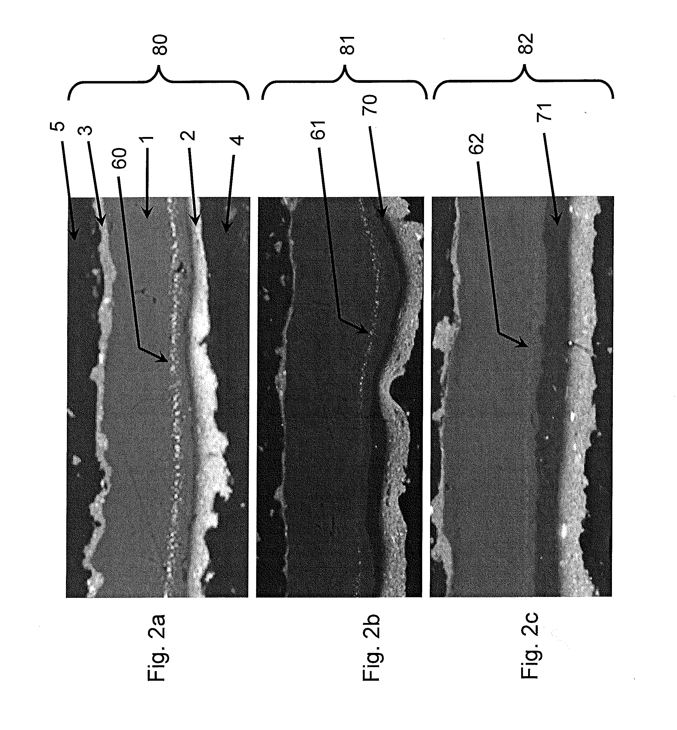
Preparation of Membrane Electrode Assembly 80

[0062]MEA 80 was prepared according to well known standard procedures. A Nafion PFSA NRE-211 membrane from DuPont was used as proton exchange membrane. It was coated with 0.25 mg / cm2 Pt catalyst loading on the cathode and 0.05 mg / cm2 Pt catalyst loading on the anode, respectively. Microporous layers on hydrophobic Toray carbon paper were used as porous anode gas diffusion layer and porous cathode gas diffusion layer.

example 2

Preparation of Membrane Electrode Assemblies 81, 82

[0063]MEAs 81 and 82 were prepared by similar procedure as described for MEA 80. However, an additional coating step was introduced to form a layer between the ion exchange membrane 1 and the cathode electrocatalyst layer 2. The coating step was performed according to a standard procedure which is, for example, usually applied during routine MEA coating steps. Said standard procedure is well known to those skilled in the art.

example 3

Assembly of Test Stacks

[0064]Three Ten-cell stacks were assembled using either MEA 80, or MEA 81, or MEA 82. The electrochemical active area of each unit fuel cell was 48.4 cm2. A subscale hardware was used in each case, i.e. carbon bipolar plate having straight parallel fuel and oxidant channels, respectively.


PUM

PropertyMeasurementUnit
electrically conductiveaaaaaaaaaa
durabilityaaaaaaaaaa
loss of poweraaaaaaaaaa

Abstract

A membrane electrode assembly for a fuel cell is disclosed, which comprises at least one porous ionomer containing layer disposed at the interface between the cathode electrocatalyst material and the ion exchange membrane of the fuel cell. The porous ionomer containing layer comprises a catalyst migration impeding compound. The membrane electrode assembly exhibits improved stability against Pt dissolution and Pt-band formation within the ion exchange membrane, hence having improved durability and lifetime performance.

Description

FIELD OF THE INVENTION[0001]The present invention relates to electrochemical fuel cells. In particular, the invention provides an improved membrane electrode assembly for a fuel cell and a fuel cell containing the improved membrane electrode assembly. The improved membrane electrode assembly comprises a porous ionomer containing layer being disposed between the membrane and the cathode and comprising a catalyst migration impeding compound.BACKGROUND OF THE INVENTION[0002]An advanced hydrogen-based fuel cell power-train system for the automotive industry must meet a number of demanding requirements to become commercially attractive. These include improvements in fuel economy, power efficiency and durability in order to provide a vehicle range equaling that of an internal combustion engine—all of which have to be achieved while trying to meet cost targets. Automotive data indicate that dissolution of the fuel cell catalyst material, in particular Pt dissolution, is a significant degra...

Claims


Application Information

Patent Timeline
Patent Type & Authority Applications(United States)
IPC IPC(8): H01M8/10
CPCH01M4/8657H01M8/1004Y02E60/521H01M2300/0094H01M2300/0082
Inventor BESSARABOV, DMITRIKUNDU, SUMITLEE, STEPHENMCDERMID, SCOTT
Owner FORD MOTOR CO
Why Eureka
Try Eureka