
Vessel and method for water treatment

Inactive Publication Date: 2006-11-30
ZODIAC POOL CARE
View PDF10 Cites 21 Cited by
  • Summary
  • Abstract
  • Description
  • Claims
  • Application Information

AI Technical Summary

Benefits of technology

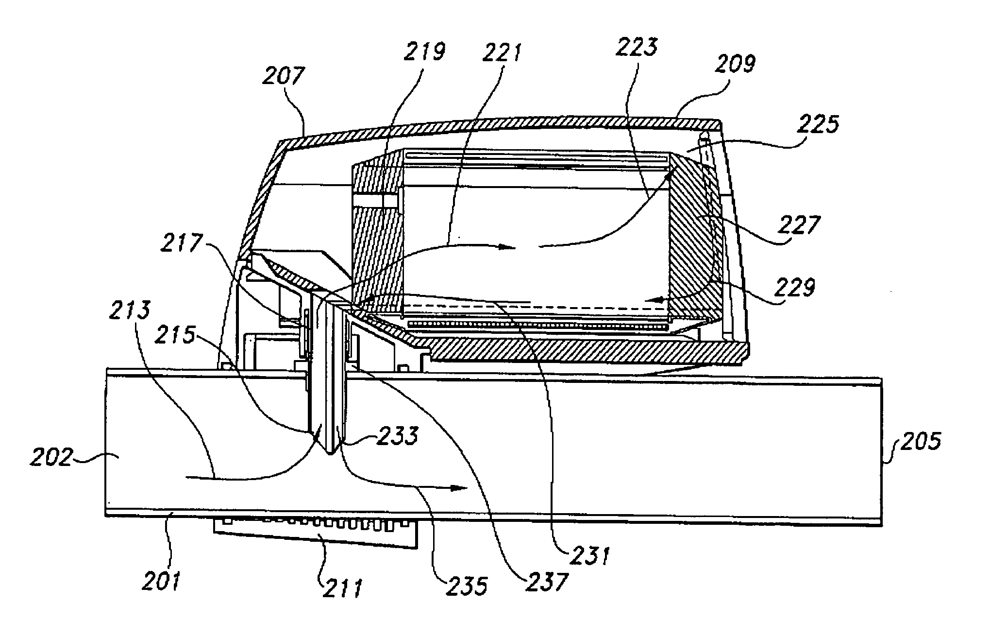
[0012] The invention relates to a vessel suitable for insertion as a by-pass into new or pre-existing fluid flow paths, such as water lines for swimming pools. The vessel is adapted to receive and contain a wide variety of different types of equipment, which can typically be in the form of a cartridge, and contact the fluid passing through the vessel with the equipment in a way that reduces or minimizes the effect of pressure spikes in the water line, and more efficiently moves the water through the vessel and back into the fluid flow path or conduit. The invention also relates to a method for treating fluids using such a vessel.
[0036] Because the design of the vessel reduces the effect within the vessel of pressure spikes in the water line, the risk of equipment damage from such pressure spikes is also reduced. This allows more sensitive equipment to be installed in fluid flow lines, whether the mechanism of the equipment is more delicate than had previously been thought possible to install, or whether the equipment can be made of less expensive, less structurally robust materials. In addition, because of its design, the vessel itself can be made of less robust, less expensive materials. The invention therefore provides for increased functionality in fluid treatment and / or monitoring, as well as for materials and design cost savings with respect to the equipment installed in the chamber.
[0037] In addition, by providing a single orifice with an inlet and outlet portion, only one opening in the fluid flow conduit is necessary to install the vessel. Fluid flow within the vessel is channeled and controlled so as to move the fluid more efficiently through the equipment and back into the fluid flow conduit, while at the same time causing the fluid to turn several times, which is believed to further limit the effect of pressure spikes on the vessel.

Problems solved by technology

However, such in-line plumbing (where all of the water in the conduit passes through the equipment, or the full flow passes by some element of the equipment as could be the case for sensors or probes, for example) can lead to equipment damage as pressure spikes, which arise due to inefficiencies in pumping, move through the conduits.

Method used


Image

  • Vessel and method for water treatment
  • Vessel and method for water treatment
  • Vessel and method for water treatment

Examples


Embodiment Construction

[0046] The invention summarized above may be more clearly understood by reference to a specific embodiment thereof shown in the attached drawings. This description and the accompanying drawings are not meant to limit the scope of the invention in any way, but are merely illustrative of the embodiments that are included within the scope of the invention.

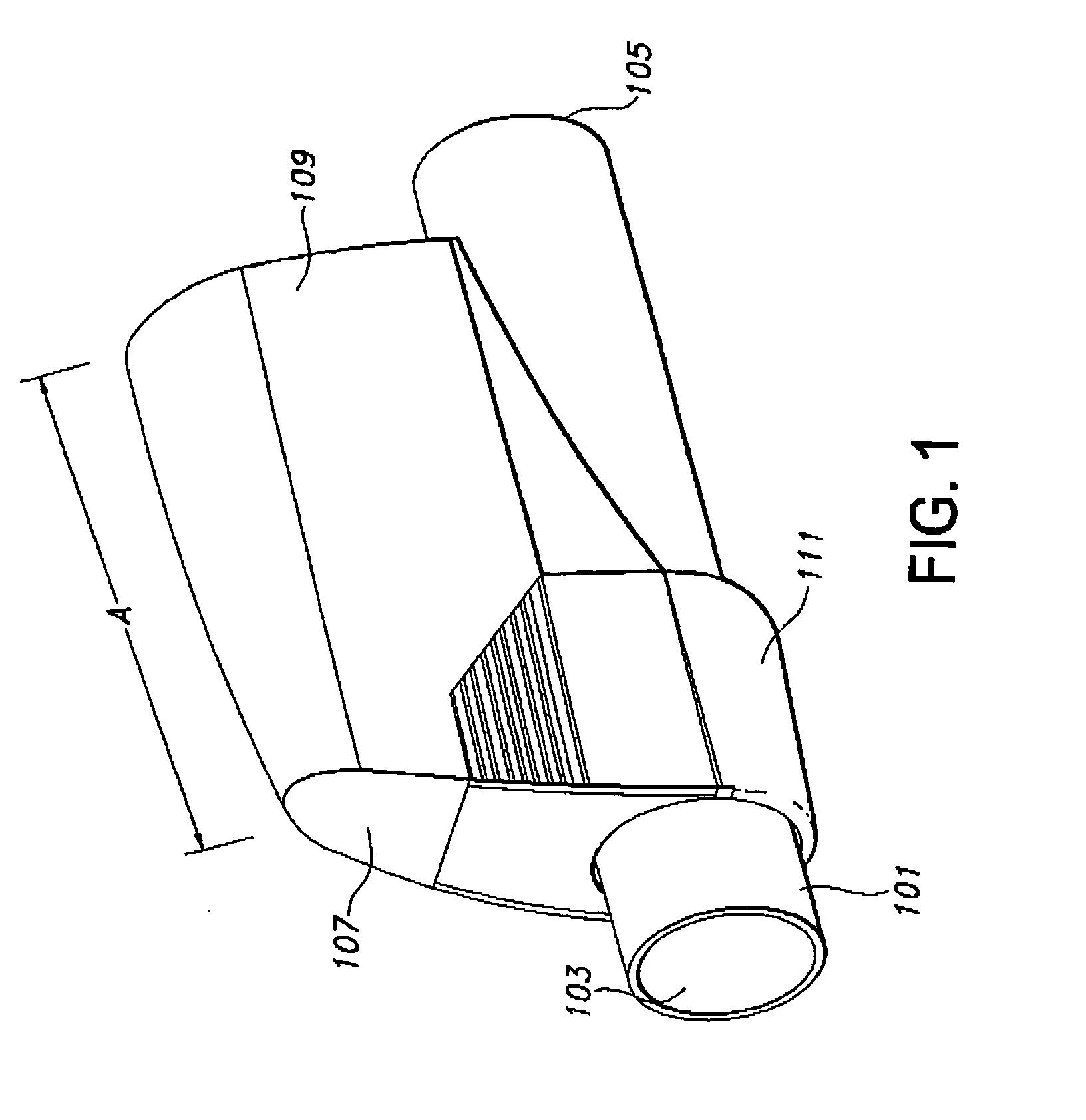
[0047]FIG. 1 shows an overall view one embodiment of the vessel of the invention in use. The vessel is attached to conduit 101, which does not itself form an element of the invention, but is included merely for the sake of clarity of explanation. Fluid, desirably water to be monitored or treated, flows in conduit 101 in the direction from area 103 to 105. Vessel 107 is rigidly attached to conduit 101 and held in place by clamp 111. Vessel 107 contains housing 109, which encloses the chamber described above.

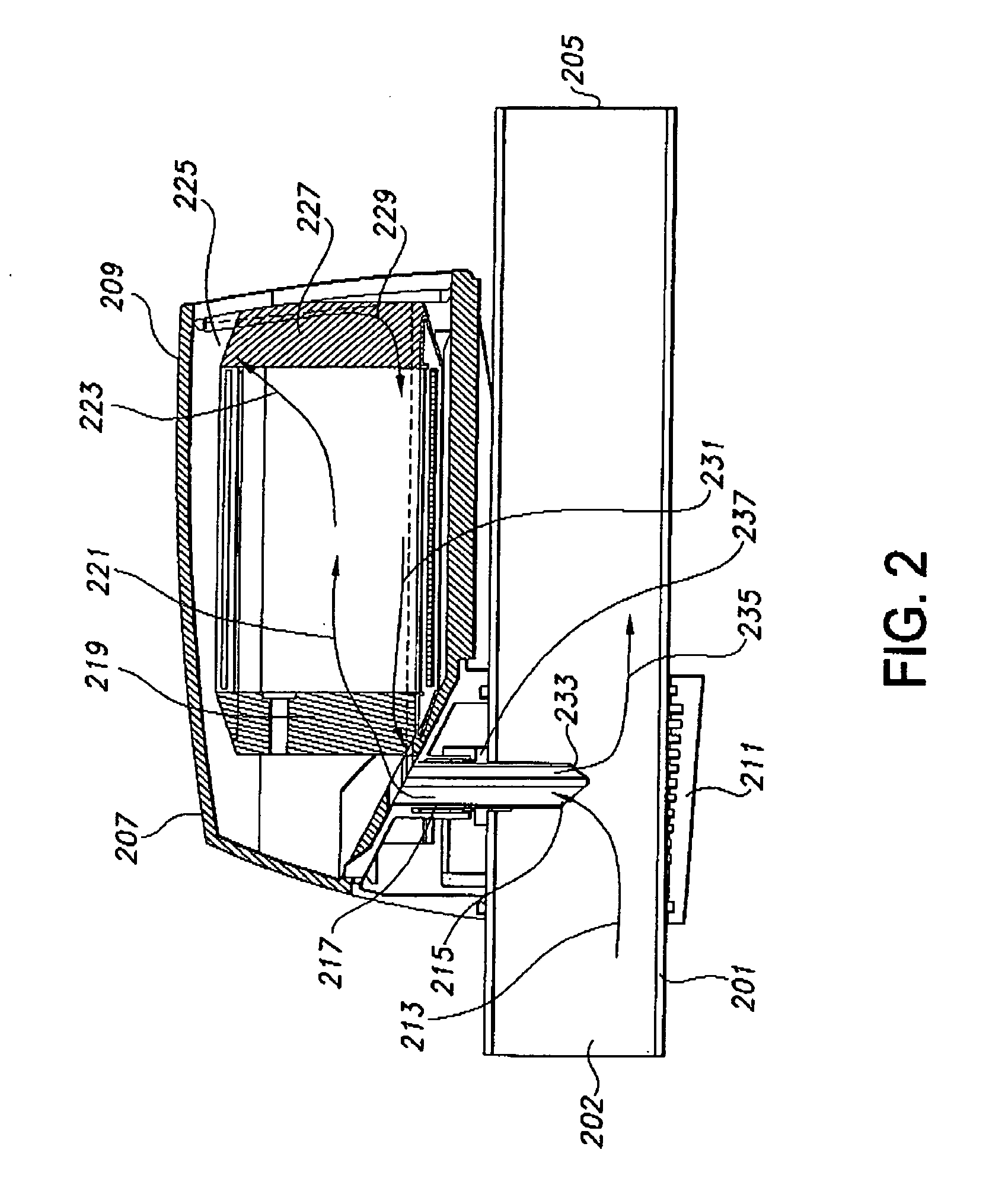
[0048]FIG. 2 shows a perspective sectional view of the vessel shown in FIG. 1 taken along line A-A of FIG. 1. Conduit 201 again ...


PUM

PropertyMeasurementUnit
Pressureaaaaaaaaaa
Water absorptionaaaaaaaaaa

Abstract

This invention relates to a vessel suitable for insertion as a by-pass into new or pre-existing fluid flow paths, such as water lines for swimming pools. The vessel is adapted to receive and contain a wide variety of different types of equipment, which can typically be in the form of a cartridge, and contact the fluid passing through the vessel with the equipment in a way that reduces or minimizes the effect of pressure spikes in the water line, and more efficiently moves the water through the vessel and back into the fluid flow path or conduit. The invention also relates to a method for treating fluids using such a vessel.

Description

[0001] This application claims priority to provisional application Ser. No. 60 / 670,383, filed Apr. 12, 2005, the entire contents of which are incorporated herein by reference.BACKGROUND OF THE INVENTION [0002] 1. Field of the Invention [0003] The invention relates to a vessel suitable for installation in a water flow path that provides a chamber adapted to receive a cartridge for water purification, testing or other water treatment processing, while decreasing the effect of sudden pressure increases or pressure spikes in the water line. The vessel can be easily inserted in existing water flow paths in virtually any orientation. The decrease in the effect of pressure spikes reduces the wear and tear on equipment contained in the chamber, and allows the equipment and vessel to be made from less expensive materials and to increase their lifetime. [0004] 2. Description of Related Art [0005] The field of fluid processing and treatment in general, and more particularly, of water treatment...

Claims


Application Information

Patent Timeline
IPC IPC(8): B01D15/00
CPCC02F1/006C02F1/28C02F1/4606C02F1/46104C02F1/4674C02F2301/043C02F1/505C02F2001/46152C02F2103/42C02F2201/006C02F2209/00C02F1/50Y10T137/8737
Inventor KENNEDY, GARY ANDREWHIN, RAYMOND ALBERTFARRER, PETER BADEN
Owner ZODIAC POOL CARE
Learn More