Flat-plate lamination-type conductive polymer actuator and flat-plate lamination-type conductive polymer actuator device as well as operating method thereof

Active Publication Date: 2010-04-22
PANASONIC CORP
View PDF7 Cites 3 Cited by
  • Summary
  • Abstract
  • Description
  • Claims
  • Application Information

AI Technical Summary

Benefits of technology

[0030]Therefore, the present invention relates to a flat-plate lamination-type conductive polymer actuator that can exert rigidity and a driving force bidirectionally in the contracting direction and in the expanding direction, and can expand displacement by lamination, and the present invention makes it possible to

Problems solved by technology

In the method of Patent Document 1, since the bimorph-type deformation is utilized, it becomes difficult to expand the displacement by further laminating a conductive polymer film, or to freely alternate the expansion of a stress.
In order to expand the displacement, the length of the conductive polymer film needs to be changed, and in order to expand the stress, the width of the conductive polymer film needs to be expanded; however, it is impossible to laminate a plurality of conductive polymer films.
In particular, the structure of Patent Document 1 makes it difficult to achieve lamination.
Thus being greatly different from a structure in which, as shown in FIG. 16A of Patent Document 1, the conductive polymer films are disposed to be made face to face in the thickness direction, this s

Method used


Image

  • Flat-plate lamination-type conductive polymer actuator and flat-plate lamination-type conductive polymer actuator device as well as operating method thereof
  • Flat-plate lamination-type conductive polymer actuator and flat-plate lamination-type conductive polymer actuator device as well as operating method thereof
  • Flat-plate lamination-type conductive polymer actuator and flat-plate lamination-type conductive polymer actuator device as well as operating method thereof

Examples


Example

First Embodiment

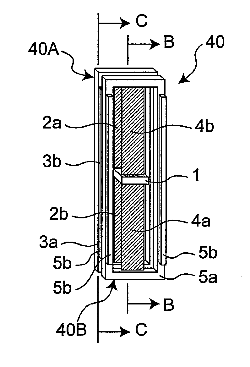
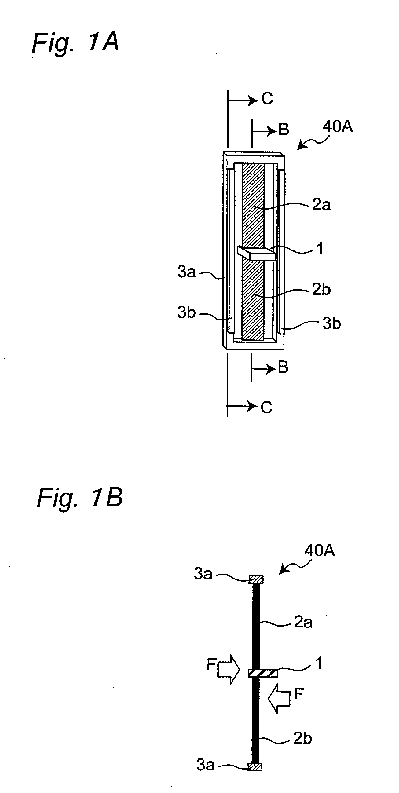
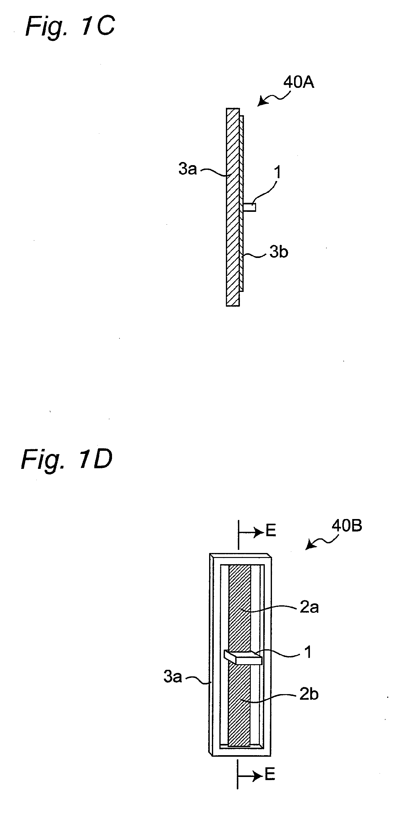
[0160]FIGS. 1A to 3C are views showing one example of a flat-plate lamination-type conductive polymer actuator in accordance with a first embodiment of the present invention and an operation method thereof. FIG. 2A is a perspective view showing the entire structure of a flat-plate lamination-type conductive polymer actuator 40 of the first embodiment. The conductive polymer actuator 40 has a structure in which a plurality (two for example) of actuator units, serving as constituent members thereof, are laminated with an electrolyte holding layer 6 (such as a first electrolyte holding layer and a second electrolyte holding layer) being sandwiched therebetween. More specifically, two first actuator units 40A are laminated (another first actuator unit 40A shown in FIG. 1A is referred to as a second actuator unit 40B, as will be described later, and in the figure, the actuator unit 40A and the actuator unit 40B are laminated) with the electrolyte holding layer 6 being san...

Example

Second Embodiment

[0178]FIGS. 4A to 4E are cross-sectional views showing one example of a flat-plate lamination-type conductive polymer actuator device 41 in accordance with a second embodiment of the present invention. Those portions of the same functions as those of the first embodiment are indicated by the same reference symbols, and overlapped description will not be repeated. Moreover, description on the case of FIG. 4F will be given later.

[0179]FIG. 4A shows flat-plate lamination-type polymer actuators 40 shown in FIG. 2B already described, which are laminated in parallel with each other with electrolyte holding layers 7 each being interposed therebetween, and the adjacent fixed frames 3a and 5 on one of the sides of the adjacent polymer actuators 40 are secured and coupled to each other by fixed frame coupling members 8 each made of an electrically insulating member. In this case, electrode wiring to the respective conductive polymer films is not illustrated because it is the ...

Example

Third Embodiment

[0190]FIG. 5A is a view showing a zero electric potential state (initial state) in one example of a flat-plate lamination-type conductive polymer actuator device 42 in accordance with a third embodiment of the present invention, that is a cross-sectional view taken along the same cutting line as that of FIG. 2B. In the flat-plate lamination-type conductive polymer actuator device 42 of FIG. 5, different from the flat-plate lamination-type conductive polymer actuator device 40 shown in FIG. 4A, upon lamination, a coupling process can be carried out on the link member 1 so as to preliminarily apply a displacement δ1 thereto, so as to set the displacement between the fixed frames to zero in a charge-applied state, and in this structure, a deformation link member 9 made of a non-insulating member that is electrically conductive is used. In each of the four flat-plate lamination-type conductive polymer actuators 40 of the flat-plate lamination-type conductive polymer actu...


PUM


Abstract

Conductive polymer films are respectively connected to fixed frames via a link member, and an electrolyte holding layer is placed so as to be made in contact with the conductive polymer films. The fixed frames are regulated by the link member.

Description

[0001]This is a continuation application of International Application No. PCT / JP2009 / 001293, filed Mar. 24, 2009.BACKGROUND OF THE INVENTION[0002]The present invention relates to a flat-plate lamination-type conductive polymer actuator and a flat-plate lamination-type conductive actuator device, as well as an operating method thereof.[0003]With the social backgrounds like the falling birthrate and the aging proportion, there have been strong demands for machines, such as home-use robots, which are operated near a person or carry out jobs in cooperation with a person. Under these circumstances, from the viewpoints of flexible movements in response to complicated jobs or ensuring safety upon collision with a person, there are high expectations for artificial muscle actuators that have flexible characteristics like muscles of the human. For such artificial muscle actuators, various materials or control systems therefor, such as those using air pressure, have been proposed. In recent ye...

Claims


Application Information

Patent Timeline
IPC IPC(8): H01L41/053H01L41/047H01L41/193
CPCA61F2002/5066G02B7/102Y10S310/80G02C7/08G02B26/0875
Inventor NAGAMITSU, SACHIOYOKOYAMA, KAZUO
Owner PANASONIC CORP
Why Eureka
Try Eureka