Control system and method for controlling two banks of adjustable vanes on a cylindrical rotor cage of an agricultural harvester

Active Publication Date: 2017-11-16
BLUE LEAF I P
View PDF2 Cites 3 Cited by
  • Summary
  • Abstract
  • Description
  • Claims
  • Application Information

AI Technical Summary

Benefits of technology

[0011]An advantage of the present invention is that the vanes are efficiently moved by a balanced adjustment s

Problems solved by technology

Variable pitch vanes within the rotor cage can bind as the van

Method used


Image

  • Control system and method for controlling two banks of adjustable vanes on a cylindrical rotor cage of an agricultural harvester
  • Control system and method for controlling two banks of adjustable vanes on a cylindrical rotor cage of an agricultural harvester
  • Control system and method for controlling two banks of adjustable vanes on a cylindrical rotor cage of an agricultural harvester

Examples


Embodiment Construction

[0020]The terms “grain”, “straw” and “tailings” are used principally throughout this specification for convenience but it is to be understood that these terms are not intended to be limiting. Thus “grain” refers to that part of the crop material which is threshed and separated from the discardable part of the crop material, which is referred to as non-grain crop material, MOG or straw. Incompletely threshed crop material is referred to as “tailings”. Also the terms “forward”, “rearward”, “left” and “right”, when used in connection with the agricultural harvester and / or components thereof are usually determined with reference to the direction of forward operative travel of the harvester, but again, they should not be construed as limiting. The terms “longitudinal” and “transverse” are determined with reference to the fore-and-aft direction of the agricultural harvester and are equally not to be construed as limiting.

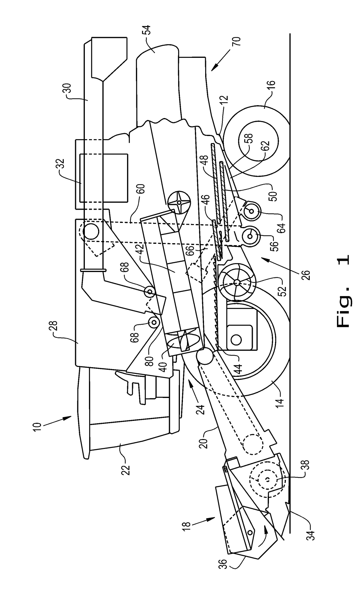
[0021]Referring now to the drawings, and more particularly to FIG. 1...


PUM


Abstract

A threshing system including a rotor cage with a plurality of slots therein, a first bank of vanes and a second bank of vanes arranged within the cage. An adjustable vane control system is coupled to the rotor cage and the banks of vanes. a first and second member are respectively pivotally coupled the vanes in the first bank and the vanes of the second bank through corresponding slots. Linkages couple an arm to the members. The first and second members each having a range of travel defined by the slots. The members each having a surface facing the outer surface of the rotor cage, the surfaces of the first member and the second member each remain tangent to the outer surface of the rotor cage as the first member and the second member are moved within their range of travel.

Description

BACKGROUND OF THE INVENTION1. Field of the Invention[0001]The present invention relates to agricultural harvesters such as combines, and, more particularly, to adjustable vane control systems used with a threshing rotor in a crop processing section of the combine.2. Description of the Related Art[0002]An agricultural harvester known as a “combine” is historically termed such because it combines multiple harvesting functions with a single harvesting unit, such as picking, threshing, separating and cleaning. A combine includes a header which removes the crop from a field, and a feeder housing which transports the crop matter into a threshing rotor. The threshing rotor rotates within a perforated housing, which may be in the form of adjustable concaves, and performs a threshing operation on the crop to remove the grain. The threshing rotor is provided with rasp bars that interact with the crop matter in order to further separate the grain from the crop matter, and to provide positive c...

Claims


Application Information

Patent Timeline
IPC IPC(8): A01F12/18A01F7/06A01F12/24A01F12/44A01F12/46
CPCA01F12/181A01F7/062A01F12/446A01F12/24A01F12/46A01D41/12A01F7/067
Inventor KEMMERER, BENJAMINLESHER, JOSHUA A.FLICKINGER, WAYNE T.
Owner BLUE LEAF I P
Why Eureka
Try Eureka