Driving device

a technology of stepping motors and driving shafts, which is applied in the direction of magnetic bodies, magnetic circuit shapes/forms/constructions, instruments, etc., can solve the problems of low output power of stepping motors, large outer dimensions of motors, and large outer dimensions of motors, and achieve low-cost, easy-to-assemble driving, and high output. , the effect of small torque loss due to friction

Inactive Publication Date: 2006-11-30
CANON KK
View PDF10 Cites 17 Cited by
  • Summary
  • Abstract
  • Description
  • Claims
  • Application Information

AI Technical Summary

Benefits of technology

[0030] The present invention provides an easy-to-assemble low-cost driving device having a thin shape wherein the dimension in the shaft direction is very small, and high output wherein torque loss due to friction is small.
[0034] The above configurations can provide an easy-to-assemble low-cost driving device having a thin shape wherein the dimension in the shaft direction is very small, and high output wherein torque loss due to friction is small.

Problems solved by technology

Accordingly, this provides a disadvantage wherein the outer dimension of the stepping motor becomes large.
Accordingly, the magnetic flux does not act upon the rotor magnet 111 effectively, resulting in a disadvantage wherein the output power of the stepping motor is low.
Accordingly, the outer dimension of the motor becomes great, and also the magnetic flux generated by electric power being supplied to the stator coil does not act upon the rotor magnet effectively.
However, in the event that a type of motor such as shown in FIG. 16 is disposed so as to be parallel to the light axis within the lens barrel of a camera, and it is attempted to be used for driving a diaphragm blade, shutter, photographing lens, or the like, this type of motor has a solid cylindrical shape, the following problems may be encountered.
The radial dimension of the lens barrel is a value obtained by adding the radial dimension of the motor to the radial dimension of the photographing lens or the radial dimension of the diaphragm opening portion, so it is difficult to suppress the diameter of the lens barrel to a sufficient small value.
Also, with this type of motor, the dimension in the light axial direction is long, so it is difficult to dispose the photographing lens near the diaphragm blade or shutter blade.
Also, the coils 301 through 303 occupy up to near the center portion of the motor, so it is difficult to dispose another part within the motor.
Further, it is necessary to provide multiple coils 301 through 303, so this provides disadvantages such as complicating power supply control to the coils 301 through 303, and increases costs.
Accordingly, in the event of employing this motor as a shutter or a diaphragm adjustment mechanism, the dimension in the light axial direction of the motor is long, so it is difficult to dispose the photographing lens near the diaphragm blade or shutter blade.
Also, the magnet is fit to a member such as the bobbin outside of the coil or the like, so friction therebetween is great, it is sometimes difficult to obtain stable performance.

Method used


Image

  • Driving device
  • Driving device
  • Driving device

Examples


first embodiment

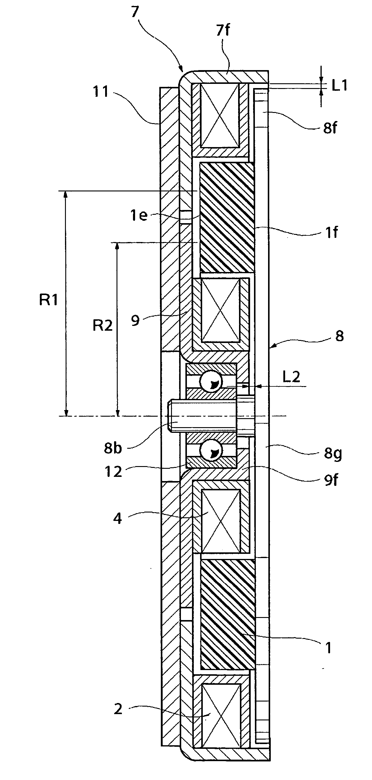
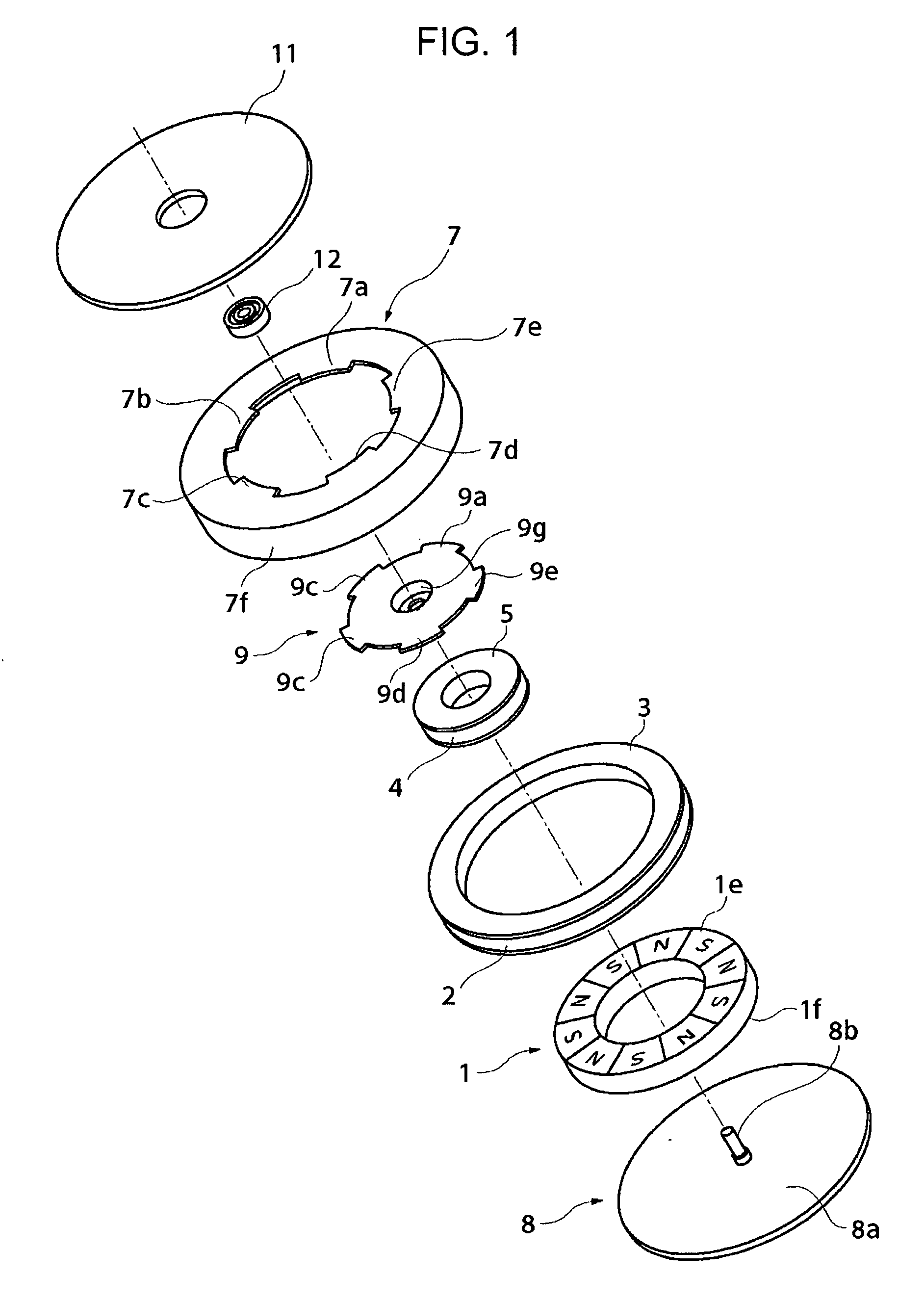
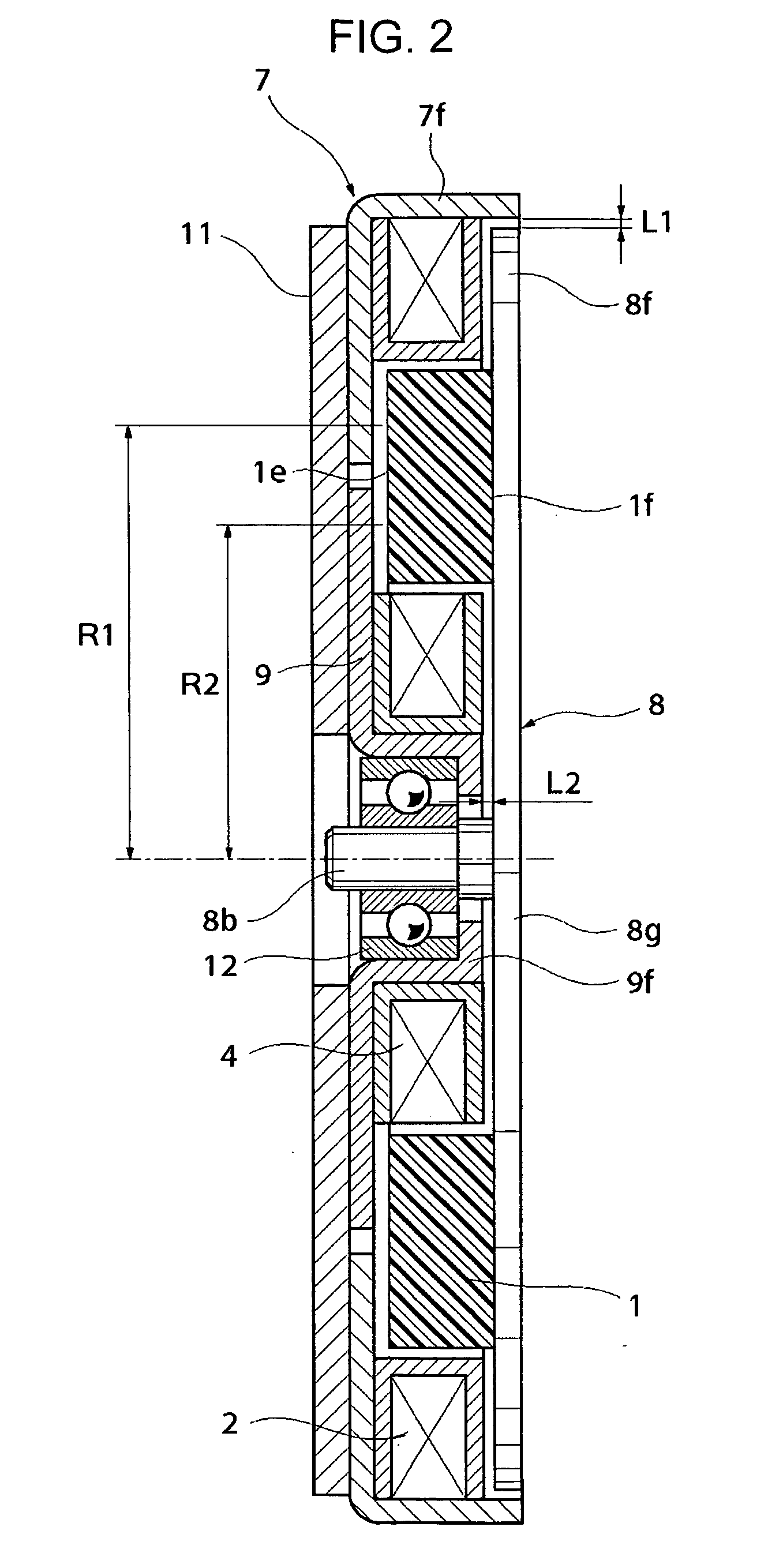
[0057]FIG. 1 is an exploded perspective view illustrating the configuration of a stepping motor serving as a driving device according to a first embodiment of the present invention. FIG. 2 is a cross-sectional view illustrating the internal configuration in the shaft direction in an assembled state of the stepping motor. FIGS. 3 through 6 are diagrams for describing the rotational action of a magnet in this embodiment.

[0058] In FIGS. 1 through 6, the stepping motor includes a magnet 1, a first coil 2, a first bobbin 3, a second coil 4, a second bobbin 5, a first yoke 7, a rotating yoke 8, a second yoke 9, a base 11, and a shaft bearing 12.

[0059] The magnet 1 is formed in a flat annular or toric shape, comprising first and second flat surfaces orthogonal to a center virtual shaft (i.e. an axis of rotation), an outer circumferential surface, and an inner circumferential surface, and also is retained with the virtual shaft serving as the rotational center so as to be rotated. Also, a...

second embodiment

[0102] The second embodiment of the present invention is different from the above first embodiment in that when citing an actuator serving as a driving device for example, the actuator has the configuration shown in FIGS. 7 and 8. With the present embodiment, the components appended with the same reference numerals as the above first embodiment (FIGS. 1 and 2) are the same as those in FIGS. 1 and 2, so the description thereof will be simplified or omitted.

[0103]FIG. 7 is an exploded perspective view illustrating the configuration of an actuator serving as a driving device according to the present embodiment, and FIG. 8 is a cross-sectional view illustrating the internal configuration in the shaft direction in an assembled state of the actuator. FIG. 9 and FIG. 10 are diagrams for describing the rotational action of a magnet. FIG. 11 is a diagram illustrating the relation between the force and rotational phase generated at the magnet.

[0104] In FIGS. 7 through 11, the actuator is fo...

third embodiment

[0148] The third embodiment of the present invention is different from the above first embodiment in that when citing an actuator serving as a driving device for example, the actuator has the configuration shown in FIGS. 12 and 13. With the present embodiment, the components appended with the same reference numerals as the above first embodiment (FIGS. 1 and 2) are the same as those in FIGS. 1 and 2, so the description thereof will be simplified or omitted.

[0149]FIG. 12 is an exploded perspective view illustrating the configuration of an actuator serving as a driving device according to the present embodiment, and FIG. 13 is a cross-sectional view illustrating the internal configuration in the shaft direction in an assembly completion state of the actuator. FIGS. 14 and 15 are diagrams for describing the rotational action of a magnet.

[0150] In FIGS. 12 through 15, the actuator is for reciprocating by disposing a coil on the inside diameter side of a magnet, and comprises a magnet ...


PUM

PropertyMeasurementUnit
bending strengthaaaaaaaaaa
polaritiesaaaaaaaaaa

Abstract

A stepping motor includes a magnet having a magnetized portion, first and second coils, a first yoke having a first-magnetic-pole portion, a second yoke having a second-magnetic-pole portion, and a rotating yoke having a third-magnetic-pole portion fixed to the single surface of the magnet. The first coil is disposed outside of the outer-circumferential surface of the magnet, and the second coil is disposed inside of the inner-circumferential surface of the magnet so as to have the same concentricity as the magnet. The first and second magnetic-pole portions and the magnetized portion face each other across a certain gap. The cylindrical portion of the first yoke and the outermost-diameter portion of the rotating yoke face each other across a gap in the radial direction, and the cylindrical portion of the second yoke and the flat surface portion of the rotating yoke face each other across a gap in the shaft direction. Thus, an easy-to-assemble low-cost driving device having a thin shape in the shaft direction, and high output with small torque loss is provided.

Description

BACKGROUND OF THE INVENTION [0001] 1. Field of the Invention [0002] The present invention relates to a driving device to be applied to a thin-disc-shaped stepping motor or actuator. [0003] 2. Description of the Related Art [0004] Heretofore, a brushless motor can be cited as a model suitable for a small motor. Examples of a brushless motor of which the driving circuit is simple include a small cylindrical stepping motor which uses a permanent magnet, such as that shown in FIG. 16. [0005]FIG. 16 is a cross-sectional view illustrating the internal configuration of a stepping motor according to a known example. [0006] In FIG. 16, a stator coil 105 is wound around a bobbin 101 concentrically, and the bobbin 101 is sandwiched and fixed with two stator yokes 106 from the shaft direction. With the stator yoke 106, stator gear teeth 106a and 106b are alternately disposed in the circumferential direction of the inside diameter surface of the bobbin 101. A stator 102 is configured in a case 1...

Claims


Application Information

Patent Timeline
Patent Type & Authority Applications(United States)
IPC IPC(8): H02K37/14H02K21/12H02K1/22H01F7/14H02K37/12
CPCH02K37/125H02K26/00H02K23/54H02K37/00
Inventor AOSHIMA, CHIKARA
Owner CANON KK
Why Eureka
Try Eureka