
Rotary electronic component

Inactive Publication Date: 2006-11-30
PANASONIC CORP
View PDF2 Cites 11 Cited by
  • Summary
  • Abstract
  • Description
  • Claims
  • Application Information

AI Technical Summary

Benefits of technology

[0015] With this structure of the present invention, the top part, which faces toward the operating knob, of the rotary contact section activated by rotating the operating knob can be sealed, even though the contact section is disposed inside the concavity with an open top. Accordingly, the present invention offers a rotary electronic component with improved dust-resistance.

Problems solved by technology

However, since a predetermined clearance is needed between operating knob 3A and hole 5A on bearing 5 in order to rotate operating knob 3A with a predetermined rotation force, it is difficult to prevent dust and moisture from entering inside to the contacts from the top.

Method used


Image

  • Rotary electronic component
  • Rotary electronic component
  • Rotary electronic component

Examples


Embodiment Construction

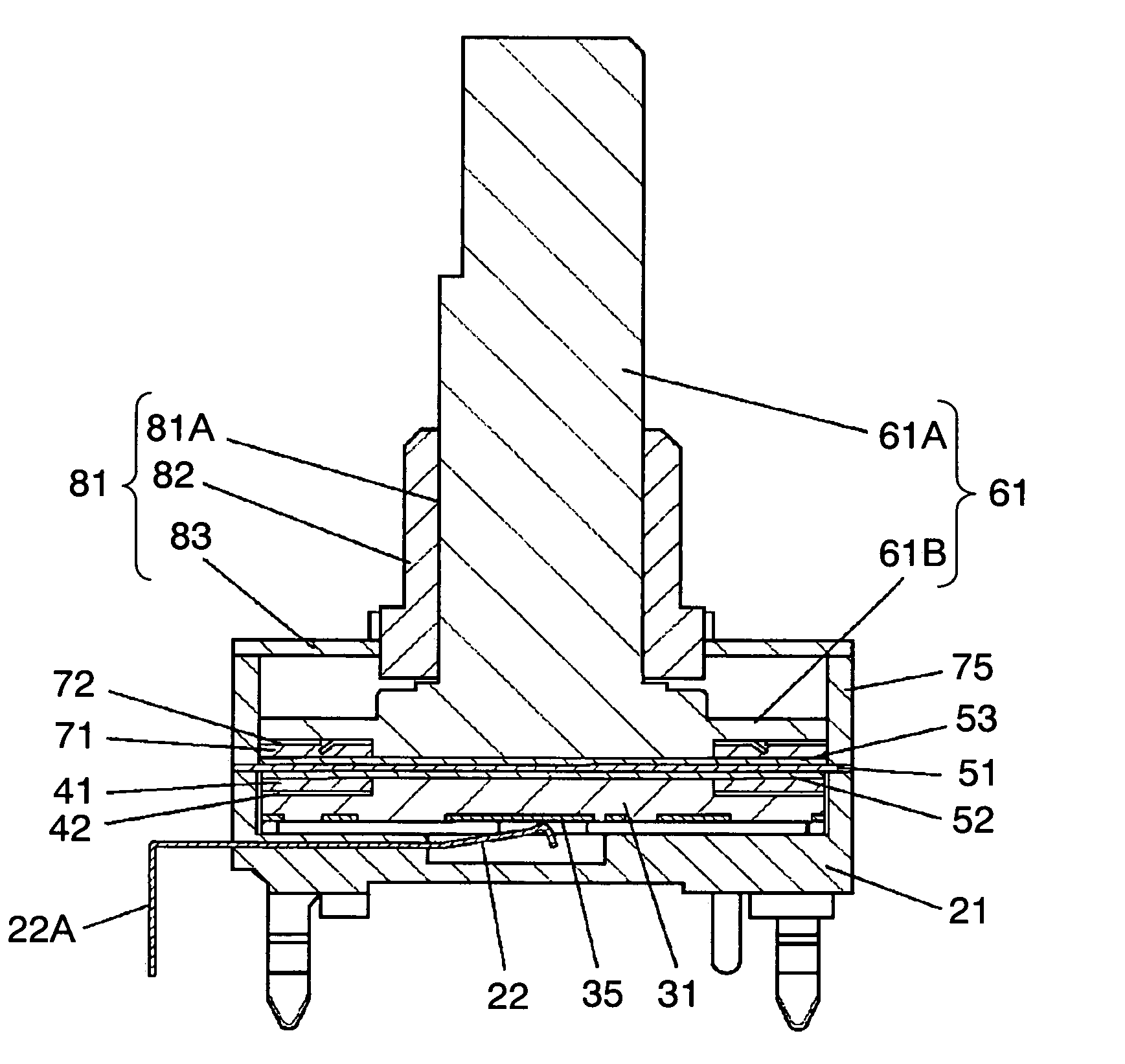
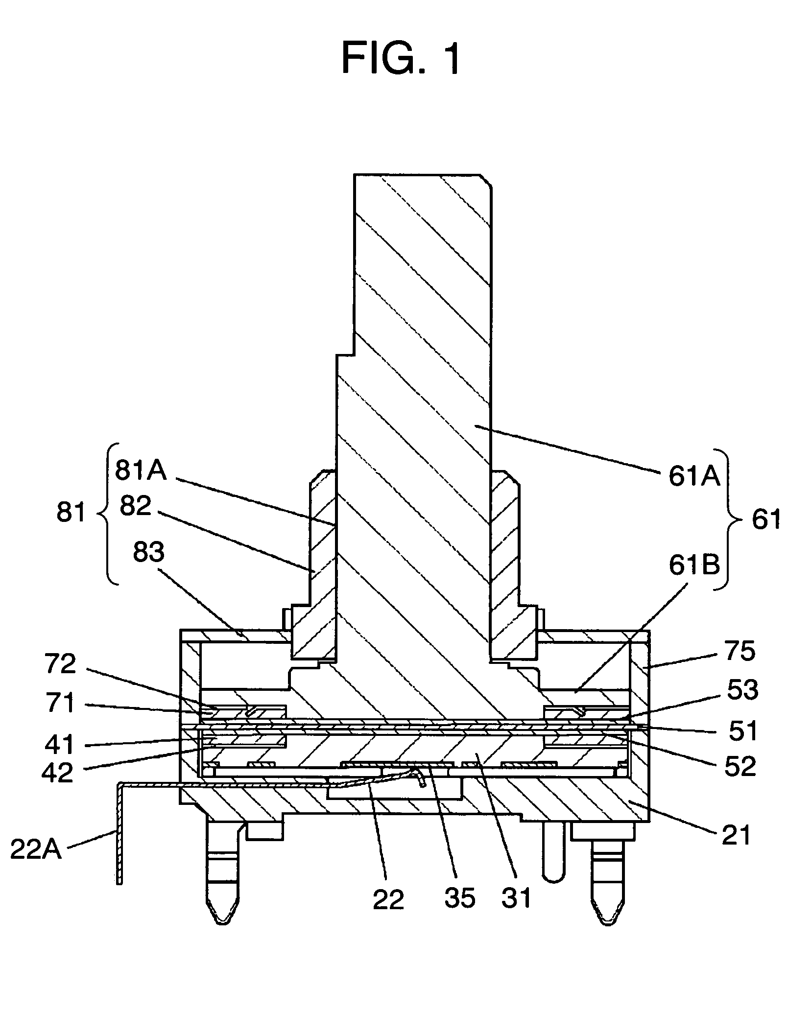
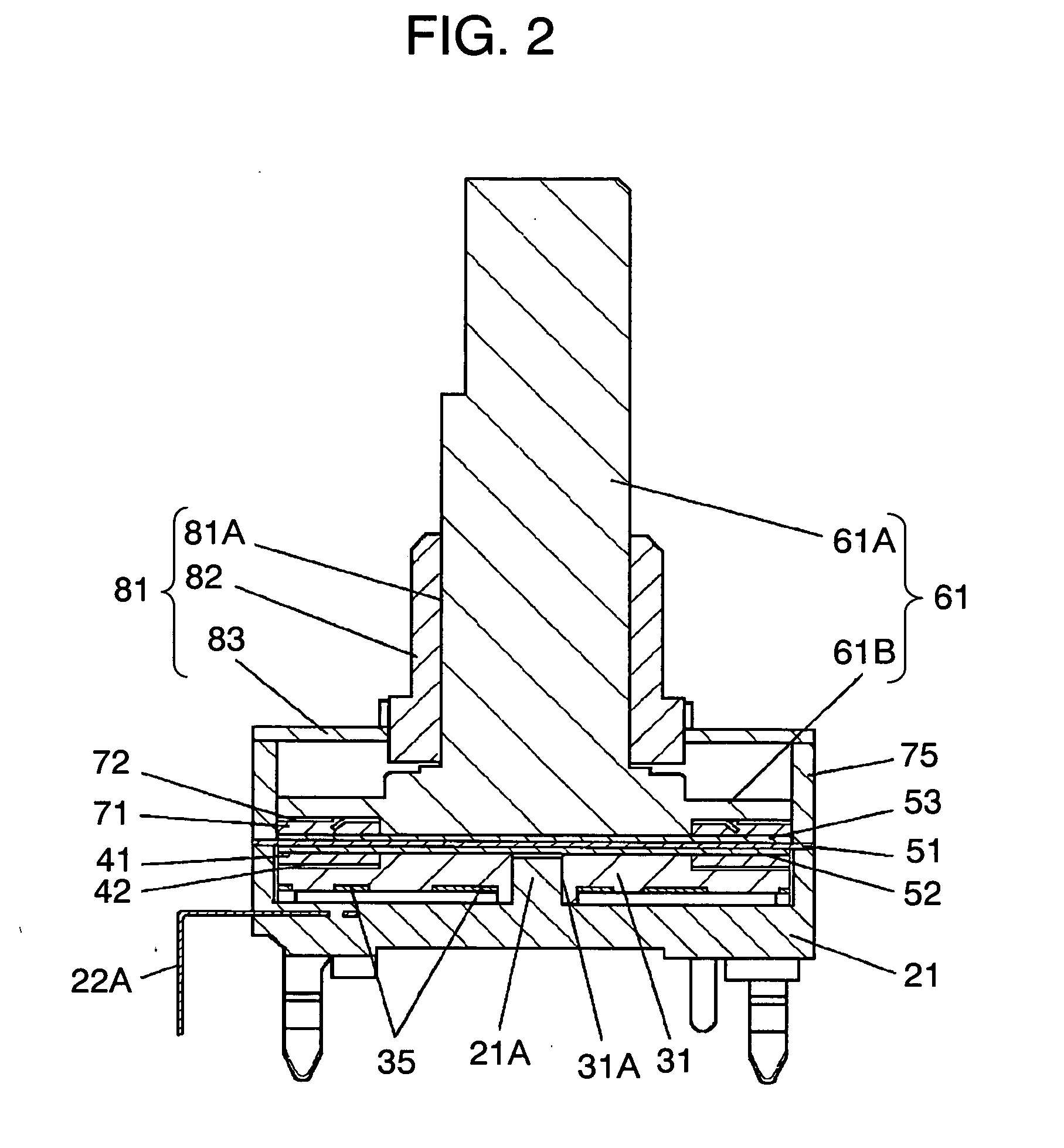
[0024]FIG. 1 is a sectional view at the position of elastic contact between a fixed resilient contact and a rotary contact of a rotary encoder in a preferred embodiment of the present invention. FIG. 2 is a sectional view at the center of the rotary encoder, and FIG. 3 is an exploded view of the rotary encoder.

[0025] As shown in FIGS. 1 to 3, case 21 is made of insulating resin, and has a concavity with an open top. Cylindrical central protrusion 21A is provided at the bottom center of this concavity. Multiple fixed resilient contacts 22 are fixed to around central protrusion 21A. The other ends of these fixed resilient contacts 22 are led out from the side of case 21 as terminals 22A.

[0026] Fixed resilient contacts 22 are fixed to this case 21 by insert molding which is a method disclosed in Japanese Patent No. 3196513. Unlike a conventional case, no through window is created at the bottom of the case, as shown in FIG. 1.

[0027] Disk-like rotor 31 made of insulating resin has cen...


PUM


Abstract

A rotary electronic component of the present invention has a sealed structure for the upper part of a contact section toward the side of an operating knob. In this structure, a rotor with a lower ring magnet is rotatably disposed on a concavity of a case with an open top. The top of this concavity is sealed with a sheet. An operating member with operating knob provided with an upper ring magnet is disposed on the sheet so that the rotor and the operating member co-rotate by the attractive force between the magnets.

Description

BACKGROUND OF THE INVENTION [0001] 1. Field of the Invention [0002] The present invention relates to rotary electronic components used for configuring an input device for electronic equipment. [0003] 2. Background Art [0004] A conventional rotary electronic component is described below, taking a rotary encoder as an example of a general structure, with reference to drawings. [0005]FIG. 7 is a sectional view and FIG. 8 is an exploded perspective view of a conventional rotary encoder. [0006] In FIGS. 7 and 8, case 1 made of insulating resin has a box shape with an open top. Round hole 1A is created at the center of its concavity. Multiple fixed resilient contacts 2 are fixed to the bottom of case 1. [0007] The other ends of fixed resilient contacts 2 are led out from the side of case 1 as terminals 2A. [0008] Flat strips of these fixed resilient contacts 2 before being bent are fixed to case 1 by insert resin molding. Then, fixed resilient contacts 2 are bent to a predetermined shape ...

Claims


Application Information

Patent Timeline
IPC IPC(8): H01R39/08
CPCH01R39/10H01R13/7037
Inventor KODANI, TAKASHI
Owner PANASONIC CORP
Learn More