Liquid-jet recording head

a liquid-jet recording and recording head technology, applied in printing and other directions, can solve the problems of a huge gap between the printing speed of high-quality recording using mainly small ink drops and the printing speed of high-speed recording using, and achieve the effects of improving the ability to supply liquid, improving the discharging frequency, and reducing the resistance of liquids

Active Publication Date: 2006-11-30
CANON KK
View PDF5 Cites 6 Cited by
  • Summary
  • Abstract
  • Description
  • Claims
  • Application Information

AI Technical Summary

Benefits of technology

[0008] Considering the problems of the related arts described above, it is an object of the present invention to provide a liquid-jet recording head with nozzles whose discharging amounts are different, the recording head discharging the smaller liquid-drops at higher frequency than the larger liquid-drops in order to improve printing speed in high-quality recording using mainly the smaller ink-drops.
[0010] Since the flow paths communicating with the first nozzles are shorter than those communicating with the second nozzles, the fluid resistance there decreases in comparison. This improves the ability to supply liquid (refilling characteristics) to the nozzles discharging the smaller liquid-drops, and makes it possible to increase the discharging frequency when the smaller liquid-drops are discharged, and to move the liquid-jet recording head at higher speed. That is to say, in such a liquid-jet recording head, high-quality and high-speed recording is achieved.

Problems solved by technology

However, there remains a huge gap between the printing speed for high-quality recording by using mainly the smaller ink-drops and that for high-speed recording by using mainly the larger ink-drops.

Method used


Image

  • Liquid-jet recording head
  • Liquid-jet recording head
  • Liquid-jet recording head

Examples


first embodiment

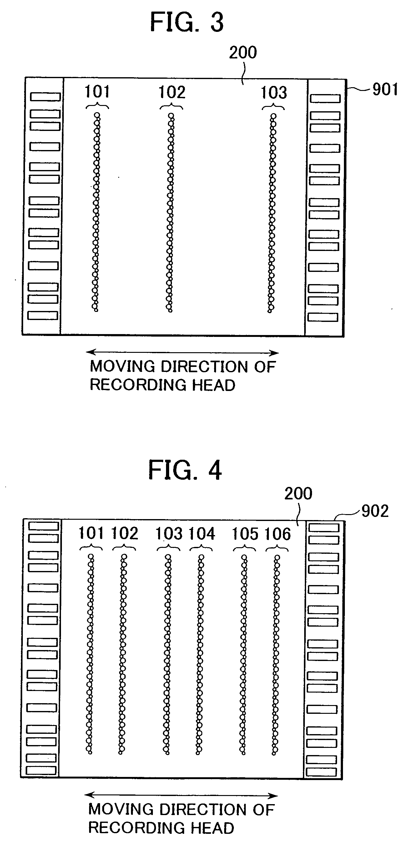
[0026]FIG. 3 is a schematic view of the ink-jet recording head of a first embodiment of the present invention viewed from the direction facing the surface where nozzles are provided. The recording head 901 shown in FIG. 3 is used for a serial printer, and it discharges two kinds of ink-drops with different volumes. Two kinds of nozzles discharging ink-drops with different volumes constitute three columns of nozzles 101 to 103 on the nozzle plate 200. The nozzle columns 101 to 103 may discharge different colors of ink. Each of the nozzle columns 101 to 103 may discharge a plurality of colors of ink. All nozzle columns may discharge the same color of ink. The number of nozzle columns is not limited to three, however.

[0027] This recording head 901 is provided on the discharging surface 903 of a head cartridge 1000 shown in FIG. 7. The head cartridge 1000 is detachably attached to a carriage (holder). The carriage is included in an ink-jet printer (not shown) and moves in the direction...

second embodiment

[0036] A second embodiment of the present invention will now be described.

[0037]FIG. 4 is a schematic view of the recording head of the second embodiment of the present invention viewed from the direction facing the surface where nozzles are provided.

[0038] The recording head 902 shown in FIG. 4 is used for a serial printer, and it discharges two kinds of ink-drops with different volumes. Two kinds of nozzles discharging ink-drops with different volumes constitute six columns of nozzles 101 to 106 on a nozzle plate 200. The nozzle columns 101 to 106 may discharge different colors of ink. In this case, the nozzle columns 101 and 102, the nozzle columns 103 and 104, and the nozzle columns 105 and 106 form pairs and discharge the same color of ink. The number of nozzle columns is not limited to six, however.

[0039] This recording head 902 is provided on a discharging surface 903 of the head cartridge 1000 shown in FIG. 7. The head cartridge 1000 is detachably attached to a carriage (...

third embodiment

[0048] A third embodiment of the present invention will now be described.

[0049]FIG. 6 shows another nozzle arrangement in the nozzle columns 101 and 102 of the ink-jet recording head 902 (described in detail in the second embodiment) shown in FIG. 4.

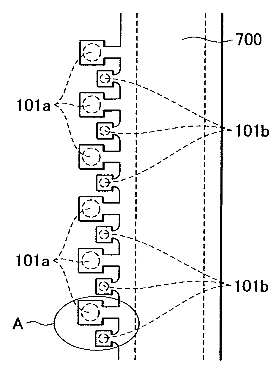
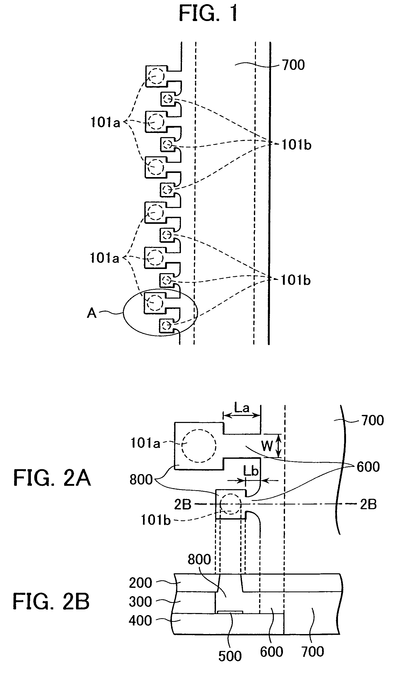
[0050] The difference between the second embodiment and the third embodiment is that every pair of nozzles facing each other across the common liquid chamber 700 discharge different amounts of ink. That is to say, a large nozzle (large ink-drop discharging nozzle) 101a in the nozzle column 101 is located directly across from a small nozzle (small ink-drop discharging nozzle) 102b in the nozzle column 102, and a small nozzle (small ink-drop discharging nozzle) 101b in the nozzle column 101 is located directly across from a large nozzle (large ink-drop discharging nozzle) 102a in the nozzle column 102. In other words, the position between adjacent large nozzles 101a in the nozzle column 101 is directly across from a large nozzle 102a in ...


PUM


Abstract

An ink-jet recording head of the present invention has two kinds of nozzles discharging different volumes of ink-drops. Large nozzles discharging the larger ink-drops and small nozzles discharging the smaller ink-drops are disposed alternately along a side of a common liquid chamber. The opening area of the large nozzles is larger than that of the small nozzles. Flow paths communicating with the small nozzles are shorter than those communicating with the other nozzles. Since the smaller ink-drops are discharged at higher frequency than the larger ink-drops, printing speed in high-quality recording using mainly the smaller ink-drops is improved.

Description

BACKGROUND OF THE INVENTION [0001] 1. Field of the Invention [0002] The present invention relates to a liquid-jet recording head for recording on recording media by discharging liquid-drops from nozzles. [0003] 2. Description of the Related Art [0004] In ink-jet printers that record images on recording media by discharging ink-drops, in order to achieve both high-quality printing and high-speed printing, it is useful to use a recording head with nozzles having different discharging amounts. [0005]FIG. 7 is a perspective view of a recording head having such nozzles. This recording head 1000 is mounted on a so-called serial printer. The serial printer prints desired images by repeating recording on recording media row-by-row while conveying the recording media in the column direction. Therefore, this recording head 1000 is movable in the direction perpendicular to the direction of conveyance of the recording media (not shown). A discharging surface 903 with a plurality of nozzle colum...

Claims


Application Information

Patent Timeline
Patent Type & Authority Applications(United States)
IPC IPC(8): B41J2/15B41J2/14B41J2/21
CPCB41J2/0456B41J2/0458B41J2/04588B41J2/1404B41J2002/14475B41J2/1433B41J2/15B41J2/2125B41J2002/14387B41J2/14145
Inventor MURAOKA, CHIAKI
Owner CANON KK
Why Eureka
Try Eureka