Liquid-droplet jetting apparatus and liquid transporting apparatus

a technology of liquid droplets and jetting apparatus, which is applied in the direction of printing and inking apparatus, etc., can solve the problems of insufficient deformation of vibration plates, inability to attenuate pressure waves in the manifold, and the strength of vibration plates is not assured, so as to achieve the effect of reducing the thickness of plates and ensuring attenuation

Active Publication Date: 2006-11-30
BROTHER KOGYO KK
View PDF7 Cites 16 Cited by
  • Summary
  • Abstract
  • Description
  • Claims
  • Application Information

AI Technical Summary

Benefits of technology

[0036] According to the second aspect of the present invention, the pressure chamber and the common liquid chamber may be adjacent, and the plate such as the vibration plate is extended from the area facing the pressure chamber up to the area facing the common liquid chamber. Furthermore, the recess is formed in the area of the plate facing the common liquid chamber, and in this area the thickness of the plate is reduced. Therefore, by the deformation of the plate, the pressure wave can be attenuated assuredly in the common liquid chamber.

Problems solved by technology

However, in an ink-jet head in the U.S. Pat. No. 5,943,079, the vibration plate being thick, the vibration plate is not deformed sufficiently, and there is a possibility that the pressure wave cannot be attenuated assuredly in the manifold.
However, when the vibration plate is made thin, a problem of strength of the vibration plate arises.

Method used


Image

  • Liquid-droplet jetting apparatus and liquid transporting apparatus
  • Liquid-droplet jetting apparatus and liquid transporting apparatus
  • Liquid-droplet jetting apparatus and liquid transporting apparatus

Examples


first embodiment

[0053] A first embodiment of the present invention will be described while referring to the accompanying diagrams. The first embodiment is an example in which the present invention is applied to an ink-jet head as a liquid-droplet jetting apparatus which jets ink from a nozzle, and as a liquid transporting apparatus.

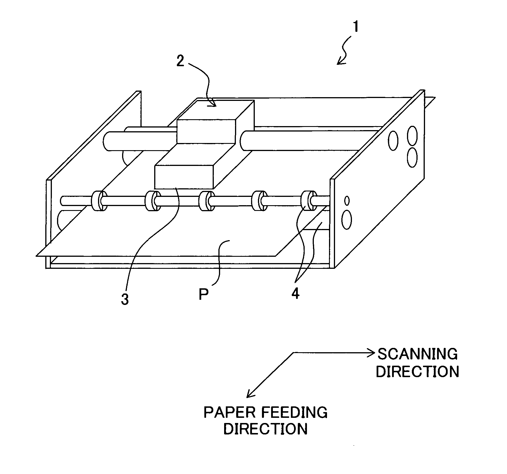
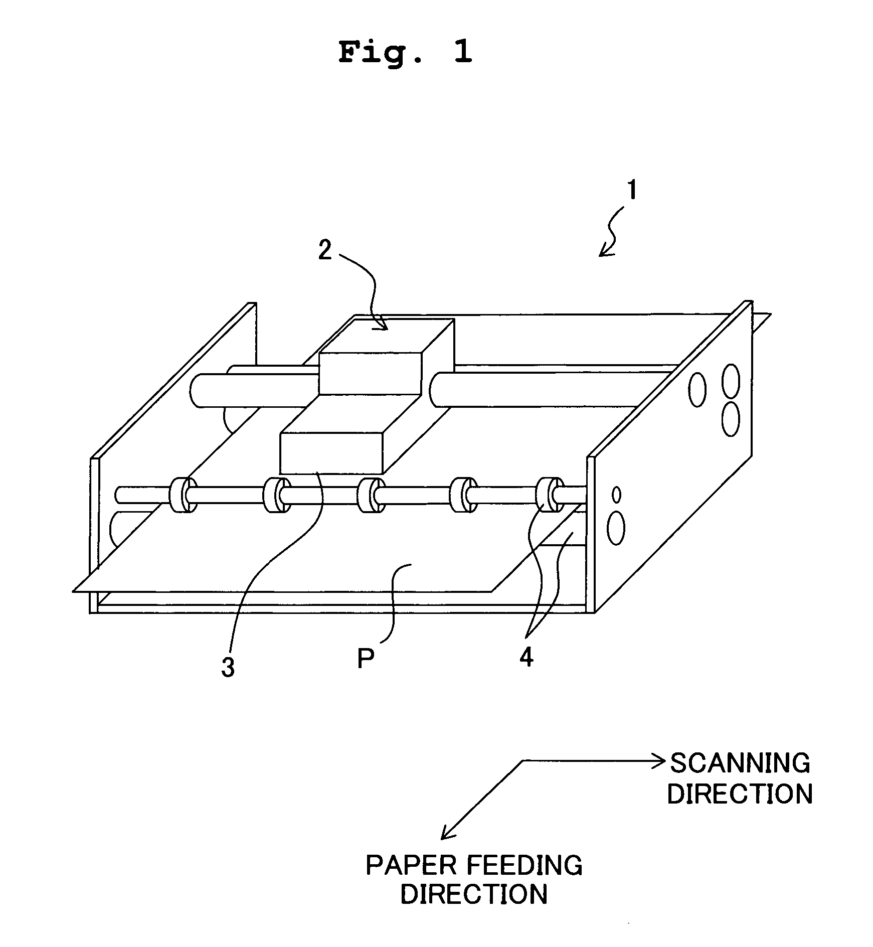
[0054] Firstly, an ink-jet printer 1 which includes an ink-jet head 3 will be described briefly with reference to FIG. 1. As shown in FIG. 1, the ink-jet printer 1 includes a carriage 2 which is movable in a left and right direction (scanning direction) in FIG. 1, the ink-jet head 3 of a serial type which is provided on the carriage 2 and discharges ink onto a recording paper P, and transporting rollers 4 which carry the recording paper Pin a forward direction (paper feeding direction) in FIG. 1. The ink-jet head 3 moves integrally with the carriage 2 in the scanning direction, and discharges ink on to the recording paper P from a nozzle 15 (refer to FIG. 2 to FIG. 5). ...

first modified embodiment

[0072] As shown in FIG. 6, a recess 85a may be formed on an upper surface of a vibration plate 85. Even in this case, the thickness of the vibration plate 85 in an area where the recess 85a is formed is reduced, and the vibration plate 85 is more susceptible to deformation (deformable) in the area of formation of the recess 85a. Therefore, the pressure wave can be attenuated in the manifold 14 by the deformation of the vibration plate 85.

Second Embodiment

[0073] The common electrode may be provided separately apart from the vibration plate 40. For example, as shown in FIG. 7, an insulating material layer 87 made of an insulating material may be formed on the upper surface of the vibration plate 40, and a common electrode 88 may be formed on an upper surface of the insulating material layer 87. In this case, the recess 40a of the vibration plate 40 being formed on a lower side, and the upper surface of the vibration plate 40 being a flat surface, the insulating material layer 87 and...

third modified embodiment

[0074] As shown in FIG. 8, a plurality of recesses 49a which is formed in a lower surface of a vibration plate 49, in an area of the vibration plate 49, facing the two manifolds 14, and extended in the paper feeding direction (a direction perpendicular to a surface of the paper in FIG. 8), and a plurality of recesses 49b which is formed on an upper surface of the vibration plate 49, and extended in the paper feeding direction, may be arranged alternately, to be lined up on the longitudinal direction of the pressure chamber 10. In this case, by forming the recesses (individual recesses) 49a and 49b, the stiffness of the vibration plate 49 in which the recesses are formed is reduced effectively, and the vibration plate 49 is made to be more susceptible to deformation.


PUM


Abstract

An ink-jet head includes a channel unit in which two sets of a manifold and five pressure chambers adjacent to the manifold are formed, a vibration plate which is provided on an upper surface of the channel unit, a piezoelectric layer which is provided on an upper surface of the vibration plate, and a piezoelectric actuator which includes individual electrodes provided on an upper surface of the piezoelectric layer, corresponding to the pressure chambers. The vibration plate is arranged such that the vibration plate covers 10 pressure chambers and two manifolds, and on a lower surface of the vibration plate, in an area overlapping with the two manifolds, a recess having a cross-sectional shape of a taper is formed. Due to the recess, a pressure wave which is propagated to the manifold can be attenuated assuredly.

Description

CROSS REFERENCE TO RELATED APPLICATION [0001] The present application claims priority from Japanese Patent Application No. 2005-153904, filed on May 26, 2005, the disclosure of which is incorporated herein by reference in its entirely BACKGROUND OF THE INVENTION [0002] 1. Field of the Invention [0003] The present invention relates to a liquid-droplet jetting apparatus which jets a liquid from a nozzle, and a liquid transporting apparatus which transports a liquid. [0004] 2. Description of the Related Art [0005] Among ink-jet heads, there is an ink-jet head in which by deforming a vibration plate by an actuator, pressure is applied to a pressure chamber which communicates with the nozzle, and ink is allowed to be jetted from the nozzle. In such ink-jet head, a pressure wave which is generated in the pressure chamber when the pressure is applied to the pressure chamber by the actuator is propagated via a manifold up to other pressure chamber communicating with that pressure chamber. D...

Claims


Application Information

Patent Timeline
Patent Type & Authority Applications(United States)
IPC IPC(8): B41J2/045
CPCB41J2/14233B41J2202/11B41J2002/14419B41J2002/14266
Inventor SUGAHARA, HIROTOISHIKAWA, HIROYUKI
Owner BROTHER KOGYO KK
Why Eureka
Try Eureka