Oil cooler

A technology for oil coolers and oil passages, applied in heat exchanger types, indirect heat exchangers, installation, etc., can solve the problems that the positions of outflow holes and inflow holes may not be consistent, and achieve manufacturing cost reduction, manufacturing cost reduction, The effect of easy processing

Inactive Publication Date: 2012-08-15
MAHLE FILTER SYST JAPAN CORP
View PDF5 Cites 8 Cited by
  • Summary
  • Abstract
  • Description
  • Claims
  • Application Information

AI Technical Summary

Problems solved by technology

[0003] On the other hand, the position of the outflow hole and the inflow hole of the other side's equipment may not necessarily coincide with the position of the inflow hole and outflow hole of the oil etc. on the oil cooler side due to restrictions on the arrangement of the equipment on the other side.

Method used


Image

  • Oil cooler
  • Oil cooler
  • Oil cooler

Examples


Embodiment Construction

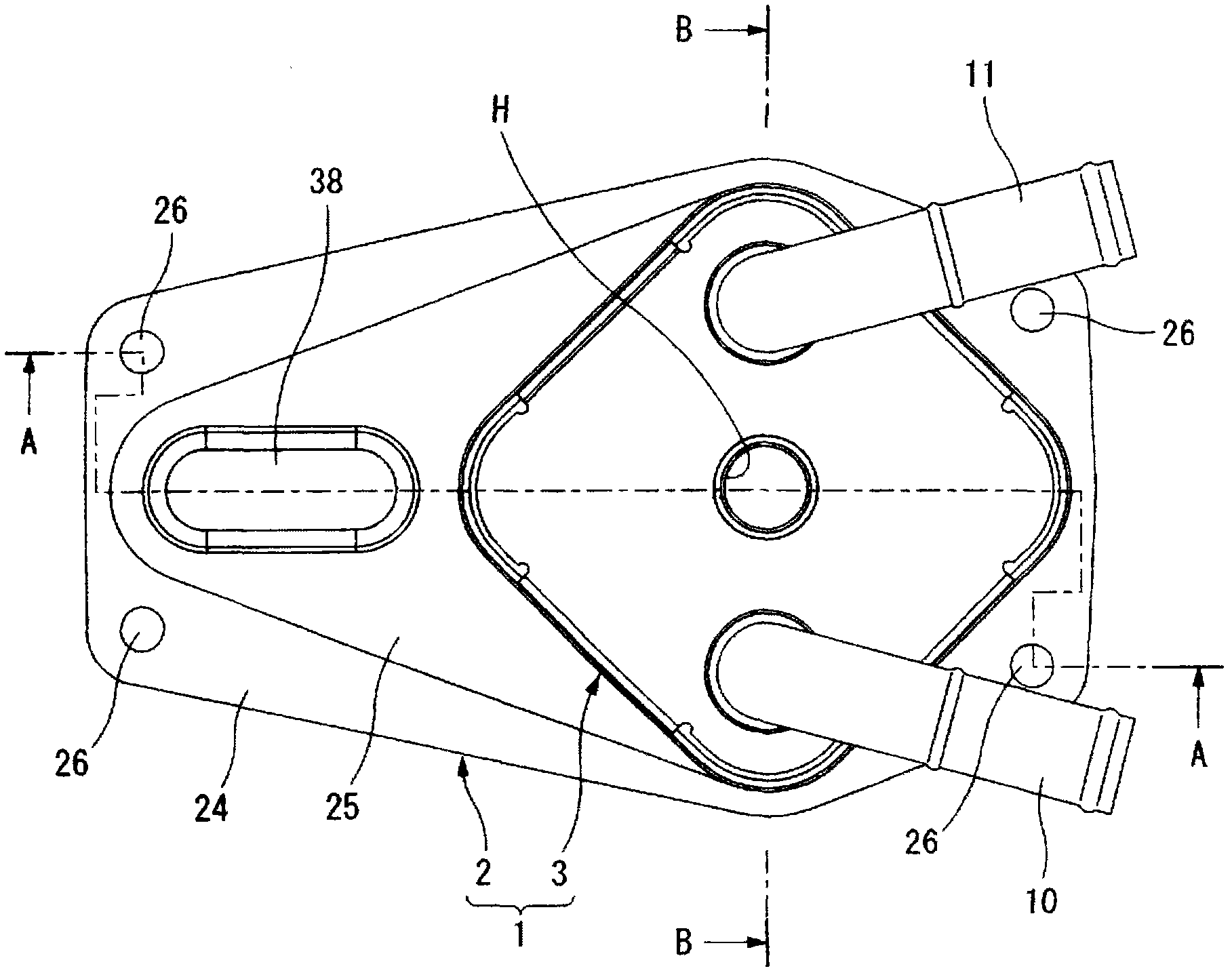
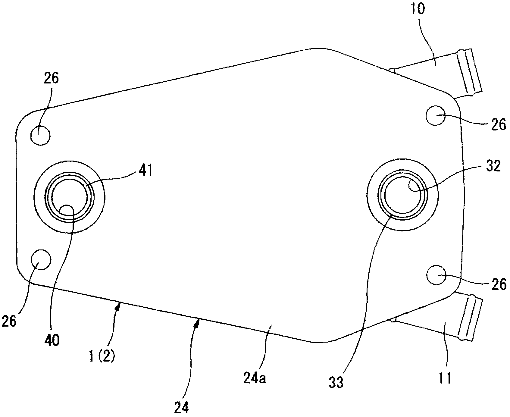
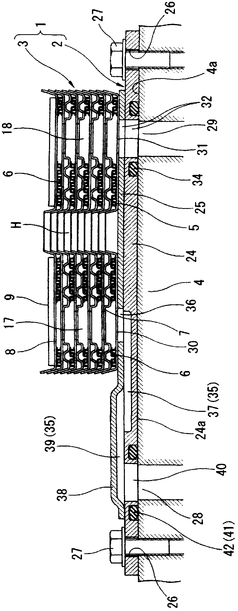
[0084] Figures 1 to 7 is a view showing a more specific embodiment for carrying out the oil cooler according to the invention, figure 1 shows the top view of the oil cooler, figure 2 Bottom view showing the same oil cooler. also, image 3 Indicated as the installed state of the above oil cooler along the figure 1 A sectional view of the A-A line, Figure 4 An exploded view showing the same oil cooler.

[0085] Such as figure 1 , 2 as well as image 3 As shown, the oil cooler 1 is composed of a laminated core 3 formed by laminating a core plate 5 , a radiator plate 6 , and an embossed plate 7 described later in multiple layers with a predetermined regularity; It is composed of two superimposed substrates 2 superposed thereon. The laminated core 3 functions as a heat exchange part as will be described later, and the substrate 2 functions as a mounting flange part for a transmission case 4 of an automatic transmission, which is a counterpart device, for example. And, ...


PUM


Abstract

In an oil cooler, oil flow inlet and oil flow outlet are respectively opened on the laminated core itself at overlapped parts of a laminated core, the laminated core constituting a heat exchanger, and a base plate, with respect to at least one of the oil flow inlet and the oil flow outlet, a corresponding oil flow input or oil flow output port being formed on the base plate to be offset toward an outside of a projection configuration region of the laminated core and an oil passage is extended within the base plate to bridge over both of inside and outside of the projection configuration region of the laminated core to connect at least one of the oil flow inlet and the oil flow outlet to the corresponding oil flow input port of the base plate or oil flow output port of the base plate.

Description

technical field [0001] The present invention relates to a structure of an oil cooler mounted, for example, on an engine block of an internal combustion engine mounted on a vehicle or a gearbox of an automatic transmission for cooling lubricating oil and operating oil. Background technique [0002] As a representative oil cooler of this type of oil cooler, there is known a so-called laminated core type oil cooler in which core plates are laminated in multiple layers. In this laminated core type oil cooler, a thick plate that functions as a mounting portion for equipment on the other side (for example, an engine block and a transmission) is provided on the lowest layer of a laminated core that is a core plate laminate. shaped substrate, and only pay attention to the flow of the cooling medium such as oil, in this case, through the flow holes formed on the substrate, the oil and the like are directly exchanged with the other side equipment. [0003] On the other hand, the posi...

Claims


Application Information

Patent Timeline
Patent Type & Authority Applications(China)
IPC IPC(8): F28D9/00F28F3/08
CPCF28D9/005F28D2021/0089F28F3/027F28F2280/06
Inventor 有山雅广
Owner MAHLE FILTER SYST JAPAN CORP
Why Eureka
Try Eureka