Liquid-droplet jetting apparatus and liquid transporting apparatus
a technology of liquid droplets and jetting apparatus, which is applied in the direction of printing and inking apparatus, etc., can solve the problems of insufficient deformation of vibration plates, inability to attenuate pressure waves in the manifold, and the strength of vibration plates is not assured, so as to achieve the effect of reducing the thickness of plates and ensuring attenuation
- Summary
- Abstract
- Description
- Claims
- Application Information
AI Technical Summary
Benefits of technology
Problems solved by technology
Method used
Image
Examples
first embodiment
[0053]A first embodiment of the present invention will be described while referring to the accompanying diagrams. The first embodiment is an example in which the present invention is applied to an ink-jet head as a liquid-droplet jetting apparatus which jets ink from a nozzle, and as a liquid transporting apparatus.
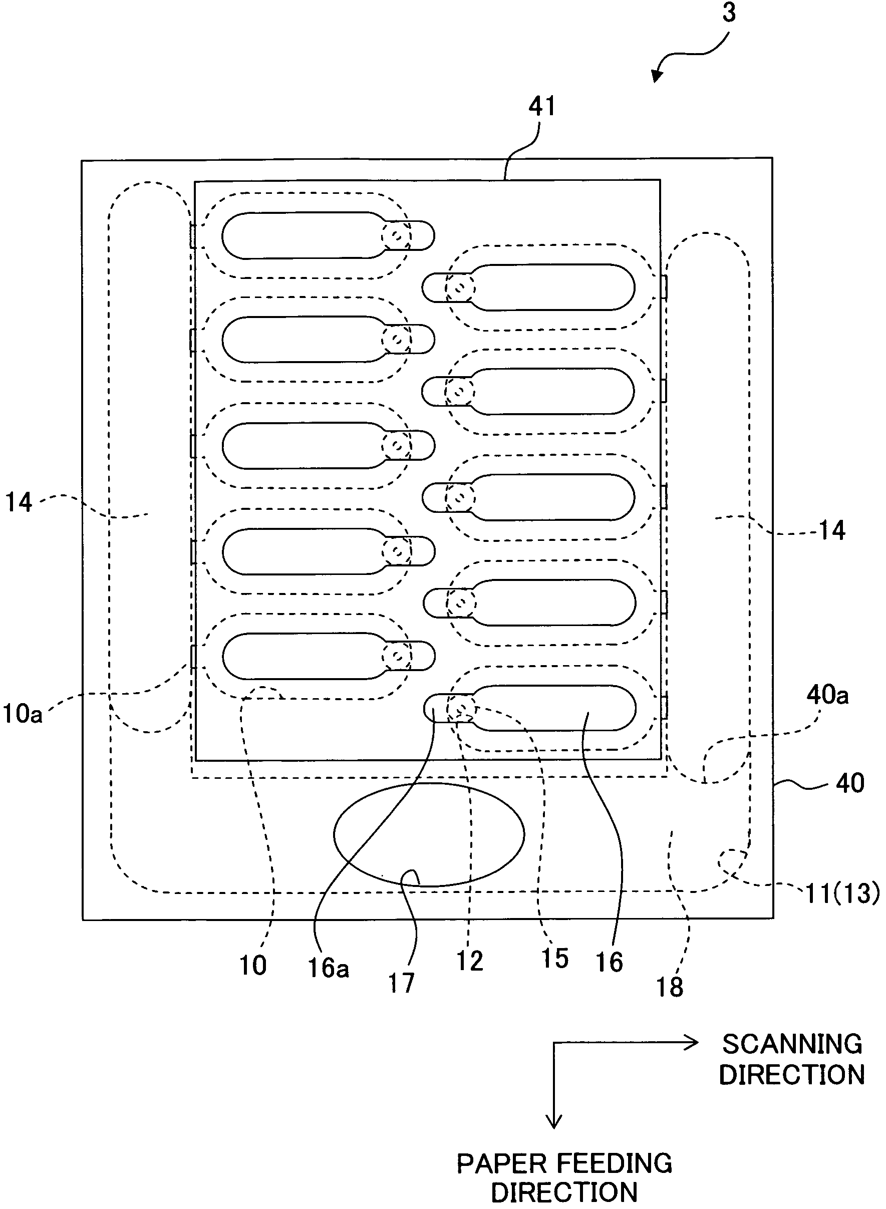
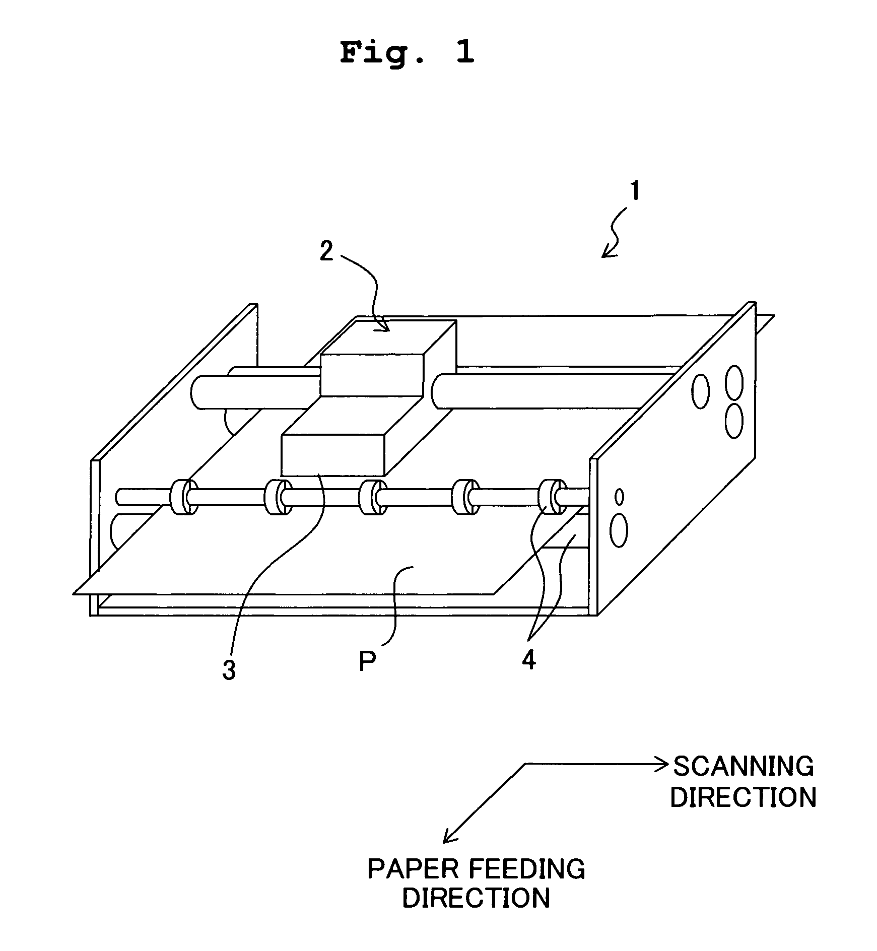
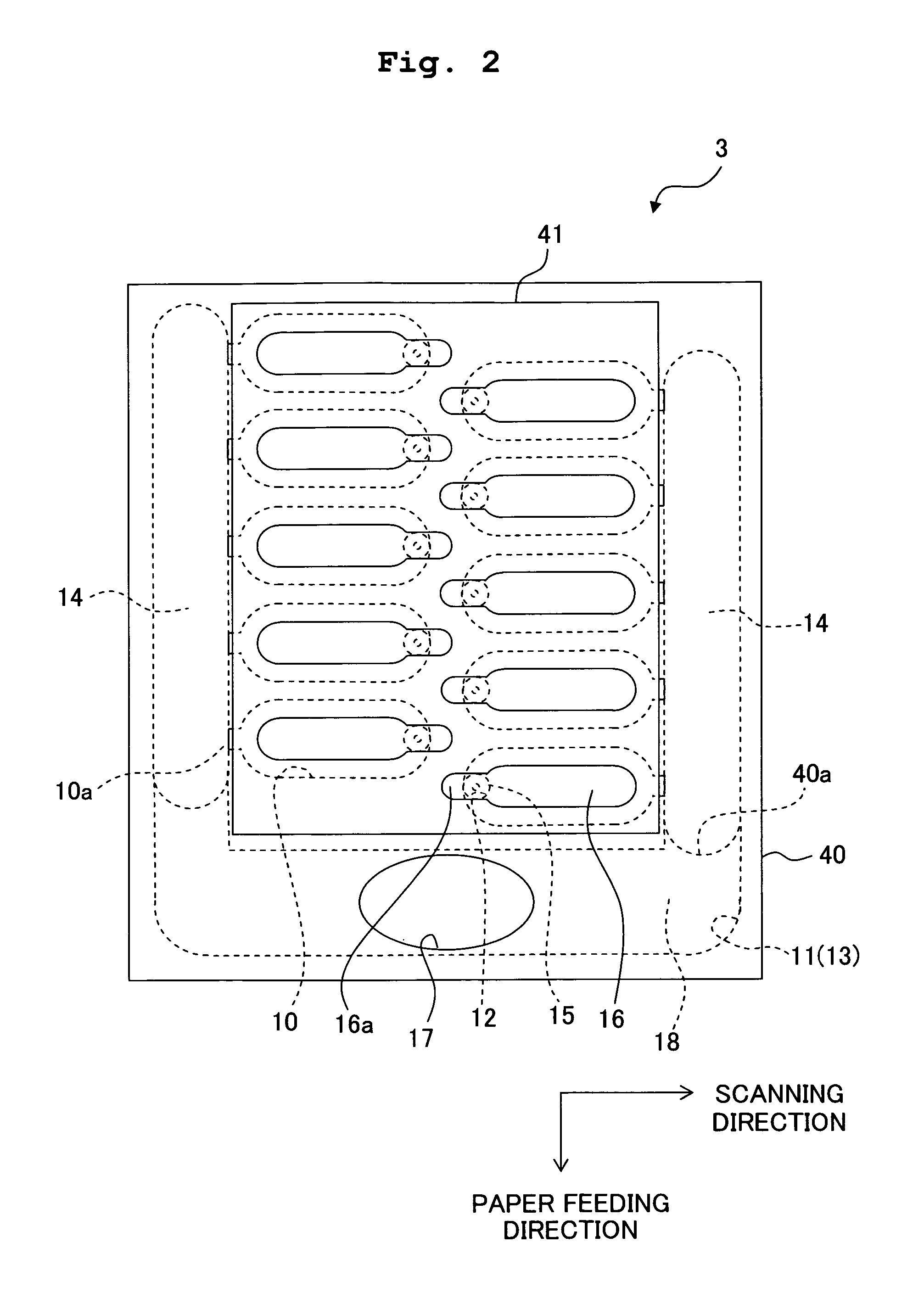
[0054]Firstly, an ink-jet printer 1 which includes an ink-jet head 3 will be described briefly with reference to FIG. 1. As shown in FIG. 1, the ink-jet printer 1 includes a carriage 2 which is movable in a left and right direction (scanning direction) in FIG. 1, the ink-jet head 3 of a serial type which is provided on the carriage 2 and discharges ink onto a recording paper P, and transporting rollers 4 which carry the recording paper Pin a forward direction (paper feeding direction) in FIG. 1. The ink-jet head 3 moves integrally with the carriage 2 in the scanning direction, and discharges ink on to the recording paper P from a nozzle 15 (refer to FIG. 2 to FIG. 5). The...
first modified embodiment
[0072]As shown in FIG. 6, a recess 85a may be formed on an upper surface of a vibration plate 85. Even in this case, the thickness of the vibration plate 85 in an area where the recess 85a is formed is reduced, and the vibration plate 85 is more susceptible to deformation (deformable) in the area of formation of the recess 85a. Therefore, the pressure wave can be attenuated in the manifold 14 by the deformation of the vibration plate 85.
Second Embodiment
[0073]The common electrode may be provided separately apart from the vibration plate 40. For example, as shown in FIG. 7, an insulating material layer 87 made of an insulating material may be formed on the upper surface of the vibration plate 40, and a common electrode 88 may be formed on an upper surface of the insulating material layer 87. In this case, the recess 40a of the vibration plate 40 being formed on a lower side, and the upper surface of the vibration plate 40 being a flat surface, the insulating material layer 87 and the...
third modified embodiment
[0074]As shown in FIG. 8, a plurality of recesses 49a which is formed in a lower surface of a vibration plate 49, in an area of the vibration plate 49, facing the two manifolds 14, and extended in the paper feeding direction (a direction perpendicular to a surface of the paper in FIG. 8), and a plurality of recesses 49b which is formed on an upper surface of the vibration plate 49, and extended in the paper feeding direction, may be arranged alternately, to be lined up on the longitudinal direction of the pressure chamber 10. In this case, by forming the recesses (individual recesses) 49a and 49b, the stiffness of the vibration plate 49 in which the recesses are formed is reduced effectively, and the vibration plate 49 is made to be more susceptible to deformation.
PUM
 Abstract
Description
Claims
Application Information
 - R&D
- Intellectual Property
- Life Sciences
- Materials
- Tech Scout
- Unparalleled Data Quality
- Higher Quality Content
- 60% Fewer Hallucinations
Browse by: Latest US Patents, China's latest patents, Technical Efficacy Thesaurus, Application Domain, Technology Topic, Popular Technical Reports.
© 2025 PatSnap. All rights reserved.Legal|Privacy policy|Modern Slavery Act Transparency Statement|Sitemap|About US| Contact US: help@patsnap.com


