Multicast control technique using MPLS

a multi-cast transmission and control technique technology, applied in the direction of digital transmission, data switching network, electrical apparatus, etc., can solve the problems of low operation efficiency, difficult to generate a distribution tree, difficult to carry out distribution for each source type, etc., to improve the management efficiency of multi-cast transmission

Inactive Publication Date: 2006-11-30
FUJITSU LTD
View PDF10 Cites 70 Cited by
  • Summary
  • Abstract
  • Description
  • Claims
  • Application Information

AI Technical Summary

Benefits of technology

[0006] Therefore, an object of the invention is to provide a technique for impro

Problems solved by technology

Accordingly, there is a problem that the operational efficiency is low.
In addition, in this case, there are problems that, precisely, it is difficult to generate a distribution tree, and that it is also difficult to carry out distribution for each source type.
Further, it is difficult to provide a multicast service, and thus to conveniently use the multicast service on-demand.
However, a technique u

Method used


Image

  • Multicast control technique using MPLS
  • Multicast control technique using MPLS
  • Multicast control technique using MPLS

Examples


Embodiment Construction

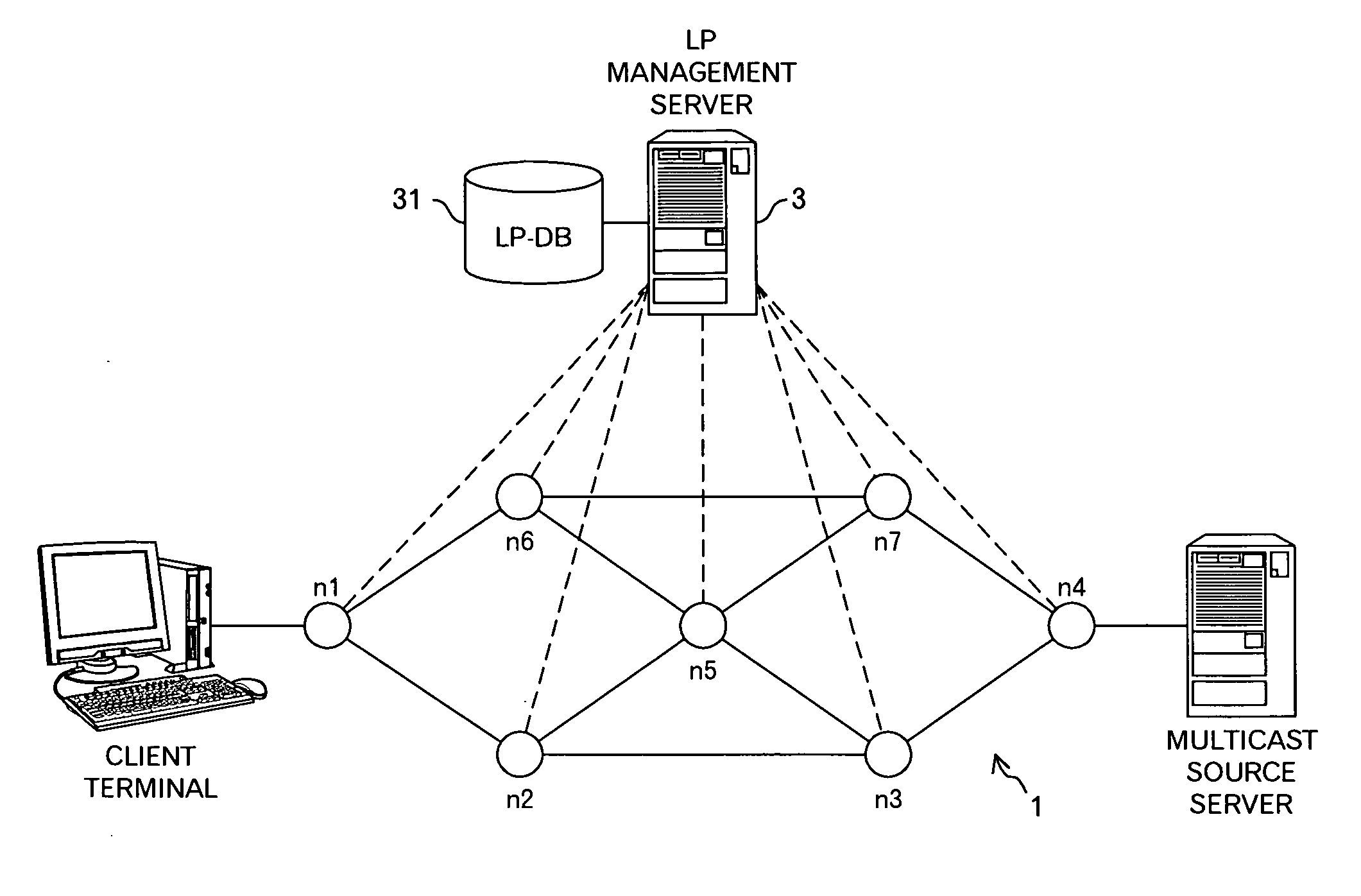
[0049]FIG. 1 is a conceptual diagram of a network according to an embodiment of the invention. In this embodiment, an LP management server 3 is connected to a network 1 including routers, such as nodes n1 to n7. The characters ‘LP’ represent an abbreviated word of a Label switched Path in MPLS (Multi Protocol Label Switching), and the LP managing sever 3 functions to determine the optimum path (LP) between arbitrary nodes in the network 1. That is, routing in the network 1 is intensively controlled by the LP management server 3, and the nodes are directly and indirectly controlled by the LP management server 3, as represented by dotted lines in FIG. 1. For such a processing, the LP management server 3 manages an LP-DB 31 storing data relating to LPs. The data stored in the LP-DB 31 will be described later in detail.

[0050] Further, for example, the node n4 is a server-side edge router connected to a multicast source server, and the node n1 is a client-terminal-side edge router conne...


PUM


Abstract

In this invention, an idea of the reverse direction label switched path (RLP) in Multi-Protocol Label Switching (MPLS) is applied to the multicast transmission to improve the management transmission in the multicast transmission, and to easily carry out an additional connection and disconnection. Specifically, in the reverse direction symmetric routing Label switched Path (LP), a virtual label in addition to an input label and an output label is used for the reverse direction routing. However, in this invention, instead of the virtual label, a multicast address to which a client terminal, which is connected to a head of the path on the reverse direction routing, and corresponds to a leaf in the multicast tree, is connected, is registered, as a multicast index, in routers on the path. Then, when receiving a multicast packet including a label and a multicast address, an output label corresponding to the received label is identified, thereby a destination link is identified.

Description

TECHNICAL FIELD OF THE INVENTION [0001] The present invention relates to a multicast transmission control technique. BACKGROUND OF THE INVENTION [0002] The routing in a conventional multicast is realized by a dedicated protocol for the multicast. In this dedicated protocol, when a connection request is received from a client terminal, it is necessary to set up a network, which is managed in a tree structure, for each additional connection. Accordingly, there is a problem that the operational efficiency is low. In addition, in this case, there are problems that, precisely, it is difficult to generate a distribution tree, and that it is also difficult to carry out distribution for each source type. Further, it is difficult to provide a multicast service, and thus to conveniently use the multicast service on-demand. [0003] Incidentally, for example, JP-A-2004-172819 discloses a technique capable of carrying out simple transmission, transmission by an explicit path, and transmission who...

Claims


Application Information

Patent Timeline
IPC IPC(8): H04L12/56H04L45/16H04L45/50
CPCH04L12/185H04L41/0896H04L45/00H04L45/16H04L45/50H04L43/0882H04L41/0897
Inventor SHIMIZU, TAKAOHOTTA, YUICHITORII, YOKOMATSUOKA, SEIJIFUJITA, YUICHISHIMAKURA, MASANOBUHARADA, MAKI
Owner FUJITSU LTD
Why Eureka
Try Eureka