Method and system for generating three-dimensional antenna radiation patterns

a technology of antenna radiation pattern and three-dimensional antenna, applied in the direction of digital transmission, transmission monitoring, instruments, etc., can solve the problems of inaccurate back pattern prediction, one half of the vertical pattern can be rotated, and the 3d back lobe may or may not match the original vertical cross section, so as to achieve the effect of reducing the disadvantages

Active Publication Date: 2006-11-30
EQUILATERAL TECH
View PDF3 Cites 14 Cited by
  • Summary
  • Abstract
  • Description
  • Claims
  • Application Information

AI Technical Summary

Benefits of technology

[0027] An object of the present invention is to provide a simple, robust, self-consistent method and / or a corresponding system for estimating three-dimensional antenna radiation surfaces from cross-sectional slices.
[0029] According to a preferred implementation of the invention, a 3D surface estimate of an antenna radiation pattern is generated using a hybrid approach—elements of a rotation technique and elements of an interpolation technique, are combined in a way that is designed to mitigate their disadvantages.

Problems solved by technology

Note, however, that it has the disadvantage that only one half of the vertical pattern can be rotated, usually the front lobe, and the other half has to be discarded.
This means that the 3D back lobe may or may not match the original vertical cross section.
In some cases this represents no problem, but in others it will predict very inaccurate back patterns, especially when the front and the back parts of the pattern have a different number of lobes.
This method requires that the horizontal pattern be fixed at the equator during the interpolation process, a requirement that, as discussed above, leads to incorrect predictions for electrically down-tilted antennas.
The front lobe, on the other hand, is clearly incorrect as this method attempts to compensate for inconsistent requirements.
This error can have a very significant effect when predicting coverage since the down-tilt is effectively cancelled by this artifact.
In addition, there is another serious problem with linear interpolation using polar coordinates—it introduces “heart” shape artifacts, especially when only a few points are available.
Any method to generate 3D patterns by interpolation will be subjected to this kind of undesirable artifact.

Method used


Image

  • Method and system for generating three-dimensional antenna radiation patterns
  • Method and system for generating three-dimensional antenna radiation patterns
  • Method and system for generating three-dimensional antenna radiation patterns

Examples


Embodiment Construction

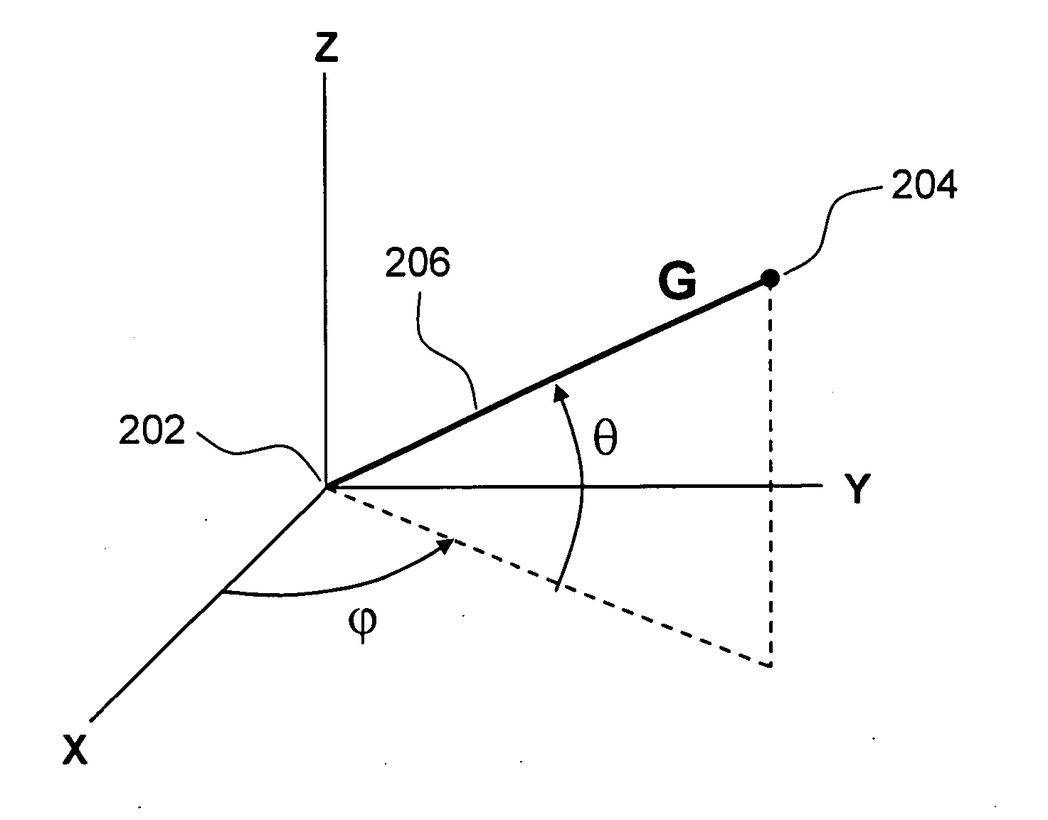
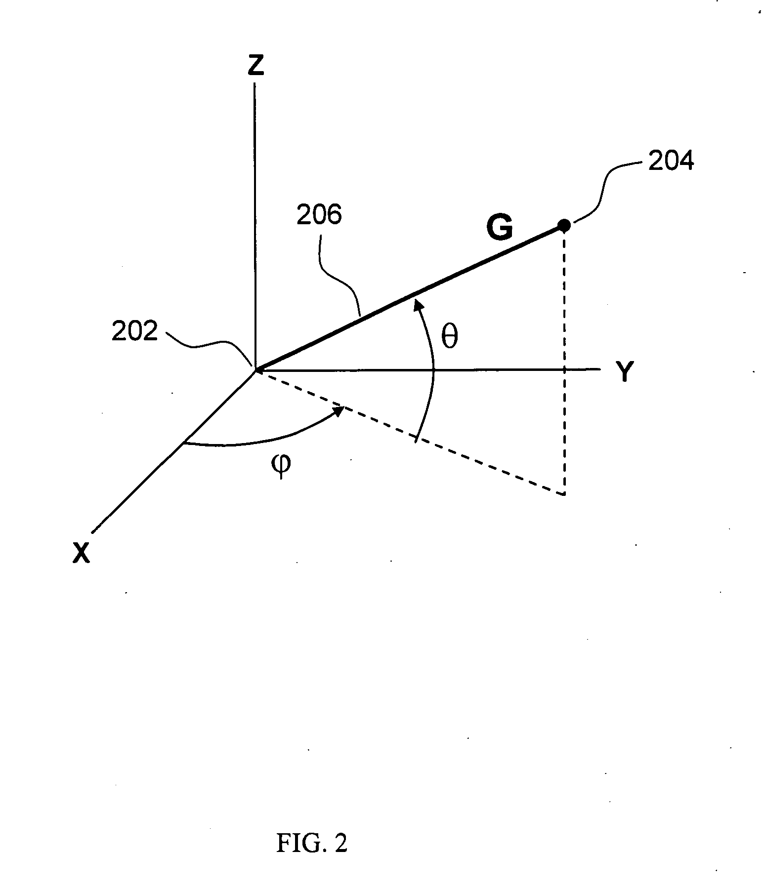
[0055]FIG. 2 shows the preferred geocentric coordinate system used with the present invention. A computational grid is prepared by specifying a θ and a φ spacing and a radius value of unity. Initially, the grid is simply the unit sphere, i.e., an isotropic antenna. As the calculation proceeds, the various radial distances on this grid will be replaced by the gain values calculated and the result will be a surface that describes the shape of the antenna pattern. For convenience, the angular spacing is usually uniform, but it can be totally arbitrary.

[0056] Although a geocentric coordinate system is preferred because it simplifies the mathematical derivation, any 3D coordinate system may be employed. FIG. 10 shows, as an example, and without loss of generality, a horizontal pattern 1004 shaped like an ellipse, placed on the X-Y plane, and an arbitrarily shaped vertical pattern 1002, placed on the Y-Z plane. The vertical pattern is shown as a vertically hatched shape.

[0057]FIG. 11 sh...


PUM


Abstract

A method and system for generating three-dimensional antenna patterns from two-dimensional cross sections. The method involves an estimate (1006), on a given vertical plane, obtained by rotating a gain value (1010) from the front of the vertical pattern using the horizontal pattern (1004) as a weight; a second estimate, which could be on a separate vertical plane, obtained by rotating a gain value (1014) from the back of the vertical pattern, and a final estimate (1206) obtained by connecting the first two estimates across their respective planes. The invention yields smooth reasonable surfaces (1704) that satisfy the vertical and horizontal boundary conditions, exhibits no mathematical artifacts, and improves the accuracy of propagation calculations of radio frequency signals. The method is implemented in a software system (1812) that provides interactive analysis and visualization capabilities for antenna patterns in three dimensions.

Description

TECHNICAL FIELD OF THE INVENTION [0001] The present invention relates to a method for generating three-dimensional antenna patterns for use in predicting radio frequency signals in wireless communication networks. More specifically, the present invention relates to the extraction of three-dimensional patterns from cross sectional two-dimensional data. BACKGROUND OF THE INVENTION [0002] The planning and optimization of wireless communications networks requires accurate propagation models. Propagation predictions are used to estimate quantities such as coverage, serving areas, interference, etc. These quantities, in turn, are used to arrive at equipment settings, such as channel assignments, power levels, antenna orientations, and heights. The goal is to optimize these settings to extract the most capacity and coverage without sacrificing the quality of the network. Thus, it is extremely important to employ a propagation model that is as accurate and reliable as possible. Naturally, t...

Claims


Application Information

Patent Timeline
Patent Type & Authority Applications(United States)
IPC IPC(8): H04L27/08
CPCH01Q1/00
Inventor VICHARELLI, PABLO A.FAGEN, DONNA
Owner EQUILATERAL TECH
Why Eureka
Try Eureka