Cutting tool, particularly for end-cut and longitudinal turning and for groove cutting

Active Publication Date: 2006-11-30
KENNAMETAL INC
View PDF11 Cites 45 Cited by
  • Summary
  • Abstract
  • Description
  • Claims
  • Application Information

AI Technical Summary

Benefits of technology

[0015] In the preferred embodiment, the cutting tool has a clamping rib that runs at a right angle to the major cutting edge and to which lateral flat surface areas are attached that are raised in relation to both the chip spaces and the chip-guiding rib. The aforementioned flat surface areas always verge on a stage on a minor cutting edge, wherein this stage can also be used as the chip curler. While this advantageously provides a stage between the longitudinal-turning chip space and the adjoining flat surface, there should be greater distance between the longitudinal-turning chip space and the clamping rib, which is positioned high when compared to the chip-guiding rib, wherein a chip that is formed at the minor cutting edge should particularly not be guided directly to the clamping rib without prior chip-breaking. This is preferably achieved by a cross rib that is connected to th...

Problems solved by technology

It is particularly problematic to design the chip-guiding ...

Method used


Image

  • Cutting tool, particularly for end-cut and longitudinal turning and for groove cutting
  • Cutting tool, particularly for end-cut and longitudinal turning and for groove cutting
  • Cutting tool, particularly for end-cut and longitudinal turning and for groove cutting

Examples


Embodiment Construction

[0027] Parts that correspond to one another or that act equally are labeled with the same reference marks in all figures.

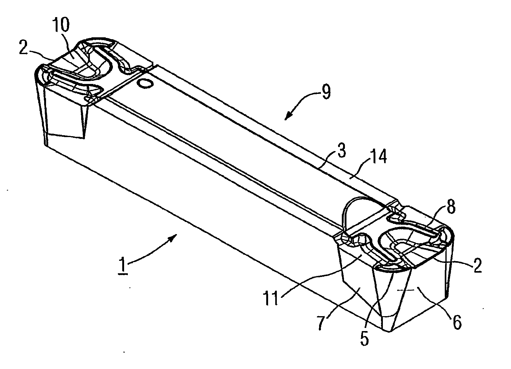
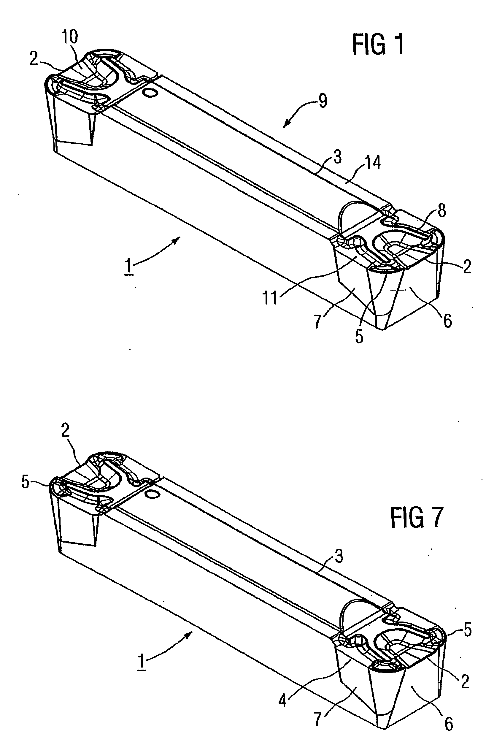
[0028] A cutting tool 1 shown in FIG. 1 is planned as a material removal tool for end-cut and longitudinal turning and is essentially designed mirror-symmetrically in the basic shape of a long, extended block with two major or end cutting edges 2 arranged on its narrow sides. A clamping rib 3 serves to clamp the cutting tool 1 that is made, for example, out of coated or non-coated hard metal. On each major cutting edge 2, two minor or side cutting edges 4 are always connected to one outer corner 5. Connected to the cutting edges 2, 4 are clearance faces 6, 7, which, in relation to the basic block-shaped form of the cutting tool 1, are placed diagonally in a way that produces a sufficient clearance angle during end-cut or longitudinal turning. A chip-guiding rib or rib structure 8 on the topside 9 of the cutting tool 1 is designed as a U-shape or a curve, wherein ...


PUM

PropertyMeasurementUnit
Fractionaaaaaaaaaa
Fractionaaaaaaaaaa
Fractionaaaaaaaaaa

Abstract

A cutting tool, such as for end-cut and longitudinal turning, and for cutting grooves in a workpiece, has an end or major cutting edge and two side or minor cutting edges, each of which are connected to the end or major cutting edge by two outer corners. An additional corner chip-breaker is formed between each of the outer corners and the ends of a chip-guiding rib. The abstract of the disclosure is submitted herewith as required by 37 C.F.R. §1.72(b). As stated in 37 C.F.R. §1.72(b): A brief abstract of the technical disclosure in the specification must commence on a separate sheet, preferably following the claims, under the heading “Abstract of the Disclosure.” The purpose of the abstract is to enable the Patent and Trademark Office and the public generally to determine quickly from a cursory inspection the nature and gist of the technical disclosure. The abstract shall not be used for interpreting the scope of the claims. Therefore, any statements made relating to the abstract are not intended to limit the claims in any manner and should not be interpreted as limiting the claims in any manner.

Description

CONTINUING APPLICATION DATA [0001] This application is a Continuation-In-Part application of International Patent Application No. PCT / EP2004 / 010588, filed on Sep. 22, 2004, which claims priority from Federal Republic of Germany Patent Application No. 103 44 961.2, filed on Sep. 27, 2003. International Patent Application No. PCT / EP2004 / 010588 was pending as of the filing date of this application. The United States was an elected state in International Patent Application No. PCT / EP2004 / 010588.BACKGROUND [0002] 1. Technical Field [0003] The present application relates to a cutting tool, particularly for end-cut and longitudinal turning, with one major cutting edge and two minor cutting edges, wherein a chip space is attached to each cutting edge, and with a curved chip-guiding rib that borders on the chip spaces and whose curve opening faces the major cutting edge. Such a cutting tool is known, for example, from DE 295 03 246 U1. The application also relates to a groove cutting tool fo...

Claims


Application Information

Patent Timeline
IPC IPC(8): B23B27/04
CPCB23B27/045B23B2200/201B23B2200/321B23B2200/323Y10T407/24Y10T407/25Y10T407/235Y10T407/245B23B2200/3663
Inventor HAVRDA, FRANZ
Owner KENNAMETAL INC
Why Eureka
Try Eureka