
Restrictor regulated air flow blanket, system utilizing such blanket and method therefor

a blanket and restriction technology, applied in the field of warming blankets, can solve the problems of expensive sensors, requiring an accompanying feedback circuit, and affecting the effect of heating air, and achieve the effect of reducing the amount of heated air in the blanket, and reducing the burden on the patien

Inactive Publication Date: 2006-11-30
SMITHS MEDICAL ASD INC
View PDF6 Cites 28 Cited by
  • Summary
  • Abstract
  • Description
  • Claims
  • Application Information

AI Technical Summary

Benefits of technology

The present invention is a patient warming blanket that automatically controls the amount of air that is allowed to pass through it, providing optimal pressurization for the patient. The blanket is fitted with a regulator or restrictor that controls the air flow rate, ensuring that the desired flow rate of air is achieved for optimal pressurization. The blanket can be connected to a convective warmer and is designed to be fitted with a regulator for each size, allowing for optimal pressurization of the blanket. The technical effect of this invention is to provide a more efficient and effective way to warm patients during medical procedures.

Problems solved by technology

However, if the convective warmer were to be used to provide heated air to a pediatric warming blanket, which has a smaller dimension than a regular adult blanket, a special hose has to be fitted to the convective warmer so that a portion of the heated air is either blocked or bypassed from the blanket.
For such feedback system, an expensive sensor, and an accompanying feedback circuit are required.

Method used


Image

  • Restrictor regulated air flow blanket, system utilizing such blanket and method therefor
  • Restrictor regulated air flow blanket, system utilizing such blanket and method therefor
  • Restrictor regulated air flow blanket, system utilizing such blanket and method therefor

Examples


Embodiment Construction

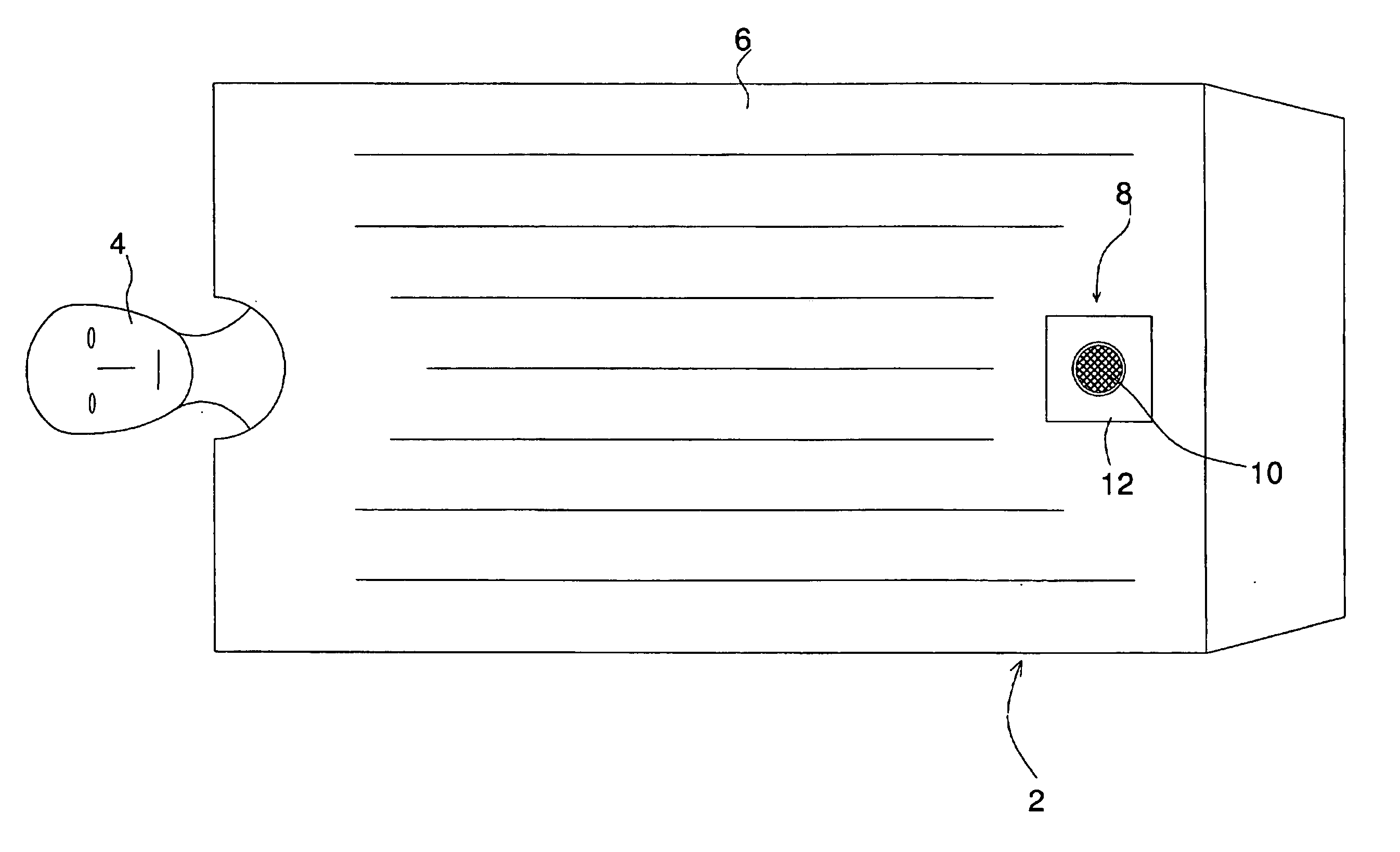
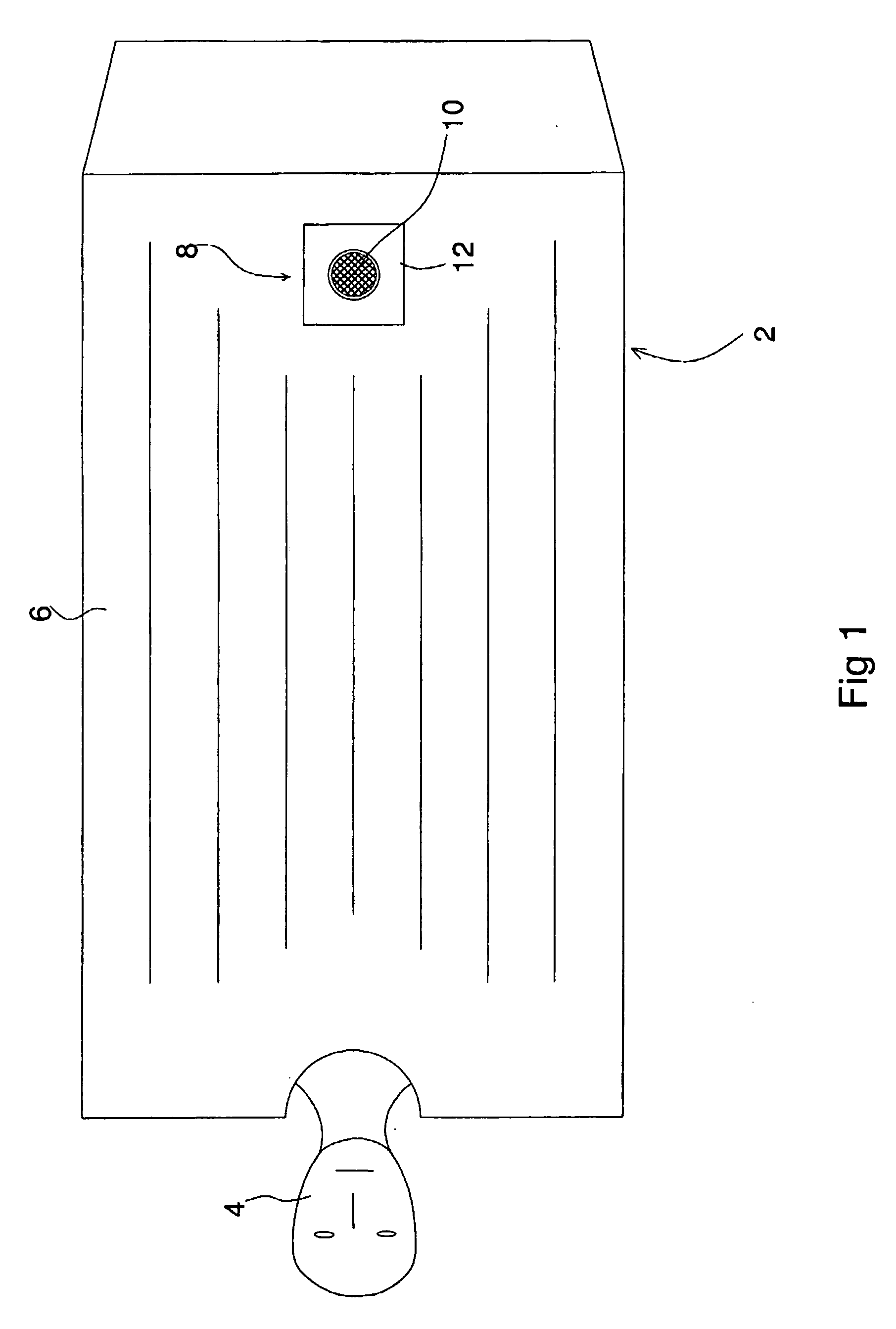
[0022]FIG. 1 is a plan view of a patient warming blanket that may be based on the blankets currently being sold by the assignee of the instant invention. For example, blanket 2 may be an adult full size blanket sold by the assignee under manufacturer No. SW-2001. Alternatively, blanket 2 may be a smaller size blanket, or may even be a neonate blanket to be used for infants and newborns.

[0023] As shown, a subject patient 4 is covered by blanket 2. As is well known, warming blanket 2 is made up of an inflatable body 6 that has two sides, the side facing the reader and a side that is in contact with subject 4. The side that is in contact with the subject has a number of openings or slits, not shown, that allow heated air in the blanket to exhaust to thereby warm or provide clinical therapy to the subject.

[0024] As shown, blanket 2 has an inlet 8 that has an opening 10 through which a fluid such as air heated by an air convection warmer is input to the blanket to inflate body 6. Inlet...


PUM


Abstract

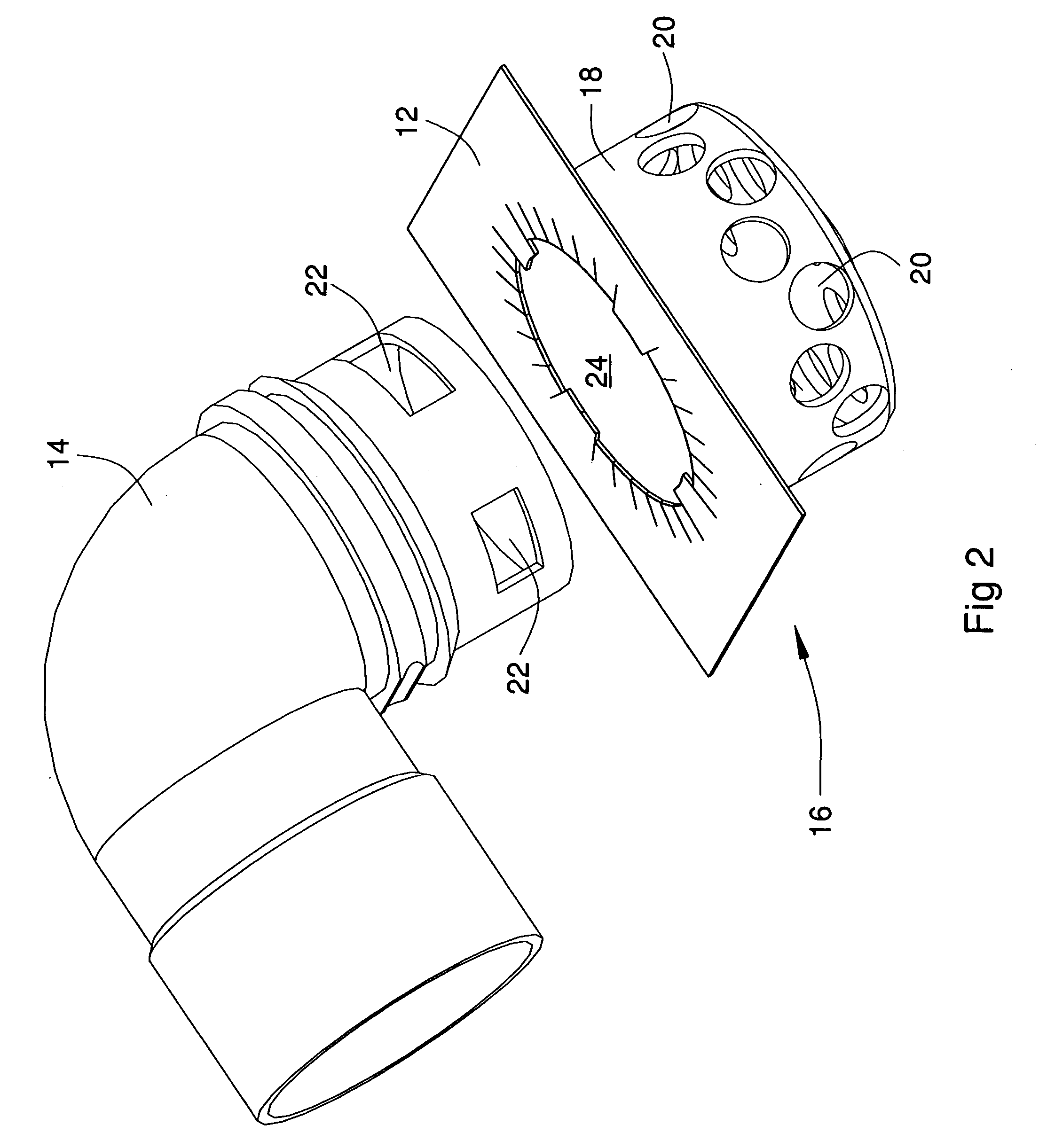
To reduce the amount of air input to a patient warming blanket, when the blanket is of a size that does not require the full amount of air output from a convective warmer for optimal pressurization, a regulator is provided to the inlet of the blanket to restrict the amount of air input to the blanket, thereby reducing the airflow rate to one that is appropriate for the optimal inflation or pressurization of the warming blanket. Respective regulators that allow different amounts of air under pressure to pass therethrough may be correspondingly fitted to blankets of different sizes and / or dimensions. Each regulator fitted to the inlet of the blanket may be configured in the form of an adapter with multiple orifices for passage of air, or a filter made of an air permeable material having a preselected porosity.

Description

FIELD OF THE INVENTION [0001] The present invention relates to warming blankets and particularly to a warming blanket that has fitted thereto a restrictor for controlling the flow rate of air input to the blanket. The present invention also relates to a system in which blankets of various dimensions each are equipped with a corresponding restrictor so that each of the blankets is adapted to be optimally inflated by the same air convective warmer, irrespective of the different dimensions of the blankets. BACKGROUND OF THE INVENTION [0002] To hypothermically warm a patient, a convective warmer to which a warming blanket is connected is used. There are various convective warming blanket types that exist in the market today. The various blankets have different dimensions. In most instances, these blankets are each inflated by a convective warmer, such as the Level 1 Equator™ warmer, that operates at only one speed. Thus, the same amount of air is output from the warmer to inflate the di...

Claims


Application Information

Patent Timeline
Patent Type & Authority Applications(United States)
IPC IPC(8): A61F7/00
CPCA61F7/0097A61F2007/006A61F2007/0001A61F7/02
Inventor FREY, WILLIAM E.
Owner SMITHS MEDICAL ASD INC
Learn More