Navigational markers in implants

a technology of navigational markers and implants, which is applied in the field of prosthetic implants, can solve the problem of not teaching the use of gyroscopes in the devices

Inactive Publication Date: 2006-11-30
JOHNSON LANNY L
View PDF64 Cites 88 Cited by
  • Summary
  • Abstract
  • Description
  • Claims
  • Application Information

AI Technical Summary

Benefits of technology

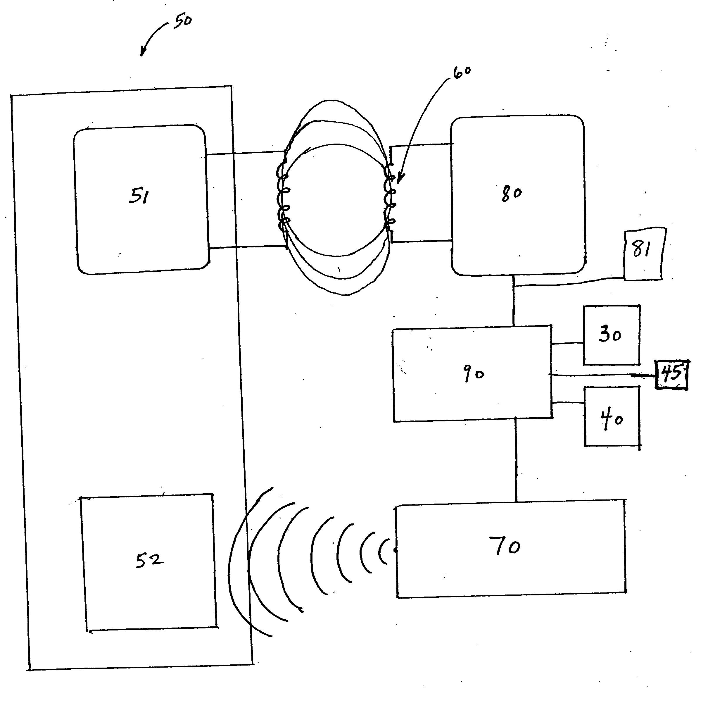
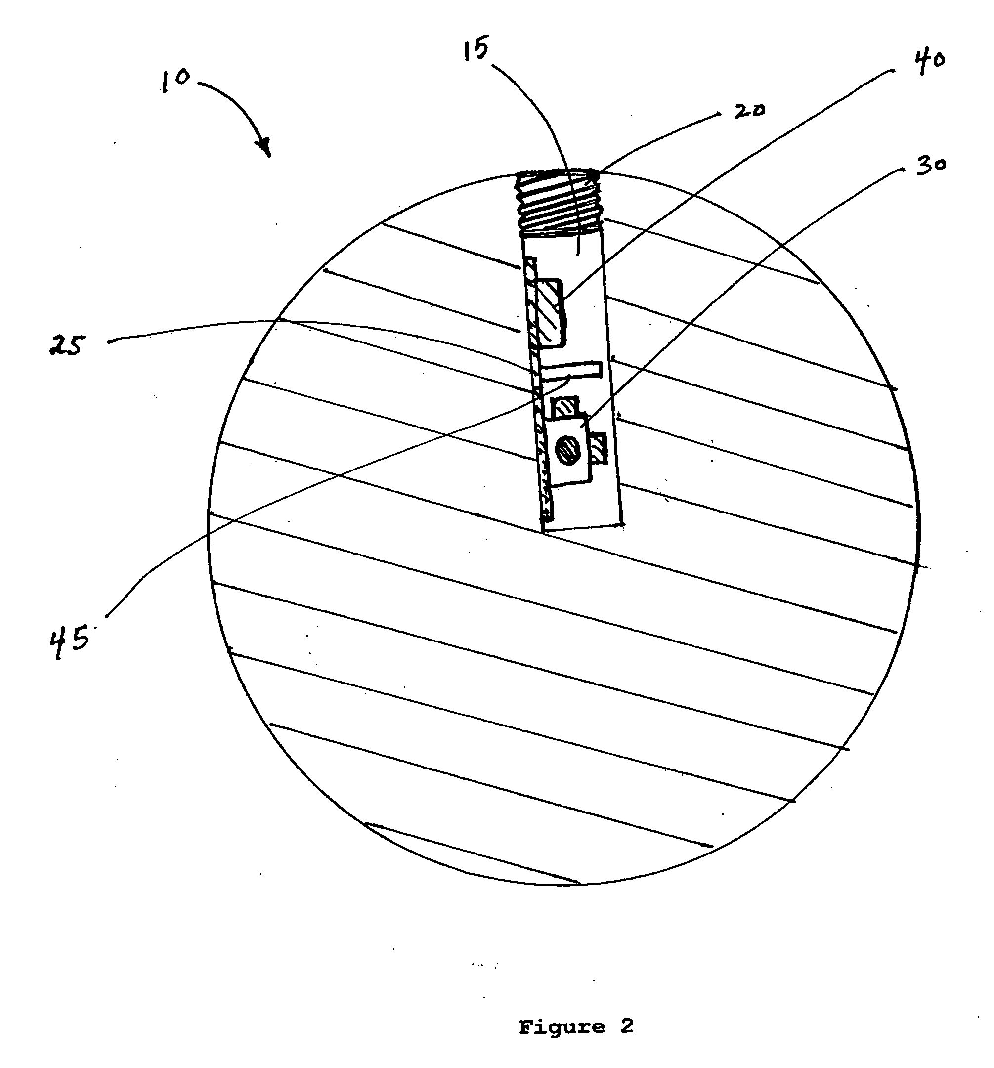
[0014] The present invention provides device for replacement of a damaged body part comprising: a prosthetic implant; and a circuit in the implant having a power element to provide power to the circuit, at least one sensor affixed to the implant comprising (1) an accelerometer to provide a sensor output in response to acceleration of the implant, (2) a gyroscope to provide

Problems solved by technology

Ishikawa et al. does not teach the

Method used


Image

  • Navigational markers in implants
  • Navigational markers in implants
  • Navigational markers in implants

Examples


Embodiment Construction

[0028] All patents, patent applications, government publications, government regulations, and literature references cited in this specification are hereby incorporated herein by reference in their entirety. In case of conflict, the present description, including definitions, will control.

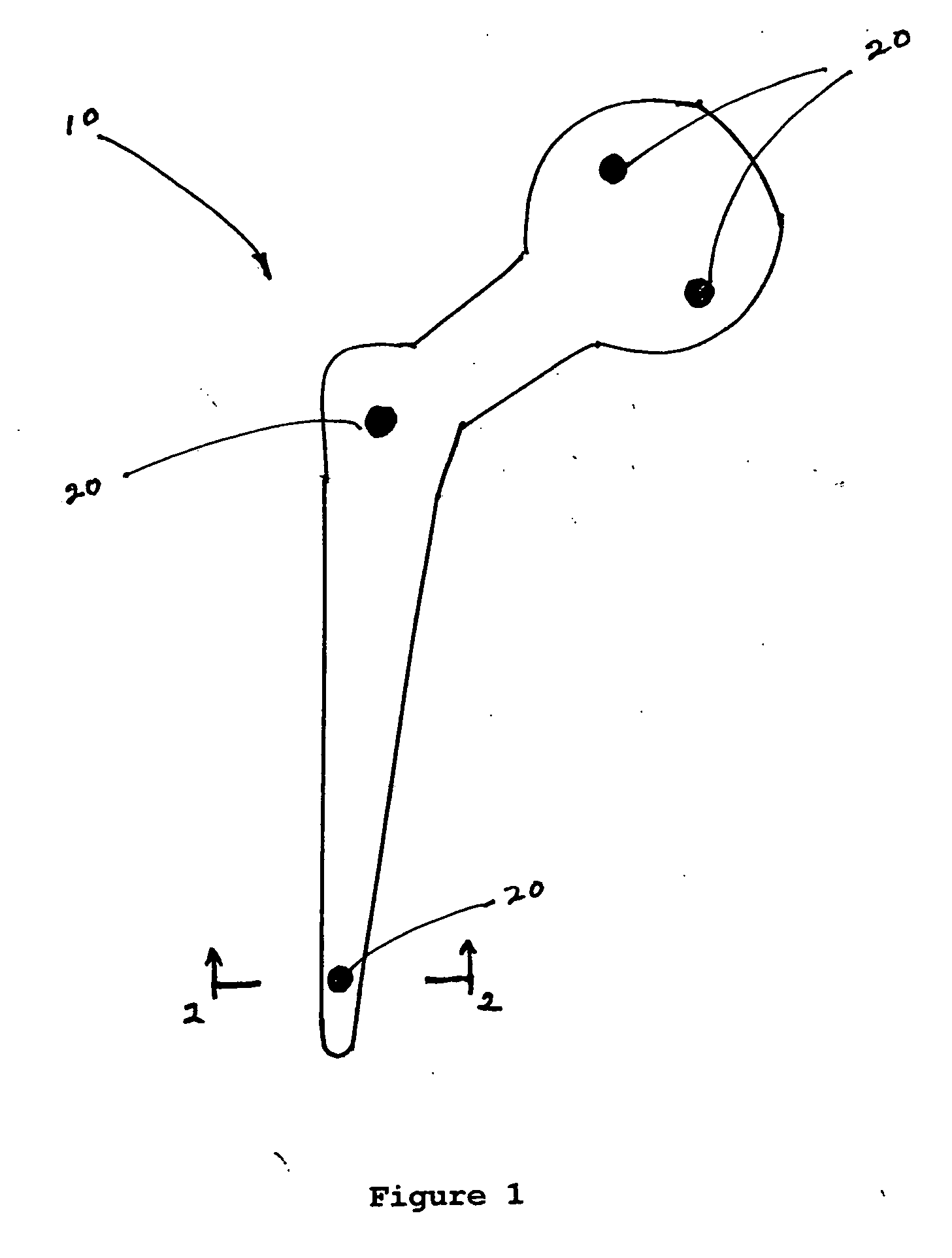
[0029] The term “prosthetic implant” as used herein refers to any device for replacing, substituting, or monitoring a damaged, worn or defective part of a patient's body. The term encompasses, but is not limited to orthopedic total joint replacement implants such as knee replacements, hip replacements, and shoulder replacements. The term also refers to dental implants.

[0030] The term “magnetometer” as used herein refers to any device which can measure the direction and / or the intensity of a magnetic field in which the magnetometer is placed, whether using the earth's natural field or an artificially created field for positioning. Generally such devices are magnetoelectric. Magnetometers providing ...


PUM


Abstract

A prosthetic implant for the body having an associated gyroscope, accelerometer and/or magnetometer as the sensor to detect changes in position of the implant. The device incorporates a miniature gyroscope, accelerometer, and/or magnetometer as a permanent part of the prosthesis for navigational information. Alternatively, the magnetometer can be external to the implant when the implant has magnetic elements associated with it. The sensors can be microelectromechanical system (MEMS) sensors placed within a drilled hole and sealed with a screw or a cap (20). The implant can be responsive to an external interrogation and powering systems. The device provides information so as to help to properly place the prosthetic implant during surgery and to assess proper functioning. The gyroscope, accelerometer, and/or magnetometer are used after implantation to provide diagnostic information in situ based upon the changed positioning or motion of the device in the prosthesis. The device can be a total joint replacement, dental implant or other type of prosthetic implant.

Description


Claims


Application Information

Patent Timeline
Owner JOHNSON LANNY L
Why Eureka
Try Eureka