Network-based robot control system and robot velocity control method in the network-based robot control system

a robot control system and robot technology, applied in the field of robot control system, can solve the problems of low processor performance, interruption of operation or error, cellular phone or pda's lower processor performance and data transmission velocity, etc., and achieve the effect of facilitating user's robot control

Inactive Publication Date: 2006-11-30
SAMSUNG ELECTRONICS CO LTD
View PDF6 Cites 92 Cited by
  • Summary
  • Abstract
  • Description
  • Claims
  • Application Information

AI Technical Summary

Problems solved by technology

For example, a PC has superior processor performance and data transmission velocity, whereas a cellular phone or a PDA has lower processor performance and data transmission velocity.
Meanwhile, a client having low processor performance and data reception velocity may fail to receive the video data frames or cannot process the received video data frames, resulting in interruption in its operation or the occurrence of an error.
However, in case of the client having low processor performance and data reception velocity, an image from the robot is not displayed smoothly and the display of the image is often interrupted because the video data frames are not received entirely at the same time and only some portions thereof are received.
As a result, the user cannot determine the current state of the robot with the image displayed on the screen of the client having low processor performance and data reception velocity, and the use will experience difficulty in controlling the robot.
In this case, an image displayed on the client having superior processing performance changes at the velocity of the robot, whereas an image displayed on the client having low processing performance changes at a velocity that is much less smooth than the movement velocity of the robot resulting in poor reception, making it difficult for users to control the robot.

Method used


Image

  • Network-based robot control system and robot velocity control method in the network-based robot control system
  • Network-based robot control system and robot velocity control method in the network-based robot control system
  • Network-based robot control system and robot velocity control method in the network-based robot control system

Examples


Embodiment Construction

[0026] A detailed construction and certain elements are provided to assist in a comprehensive understanding of an exemplary embodiment of the invention. Accordingly, those of ordinary skill in the art will recognize that various changes and modifications of the embodiment described herein can be made without departing from the scope and spirit of the invention. Also, descriptions of well-known functions and constructions are omitted for clarity and conciseness.

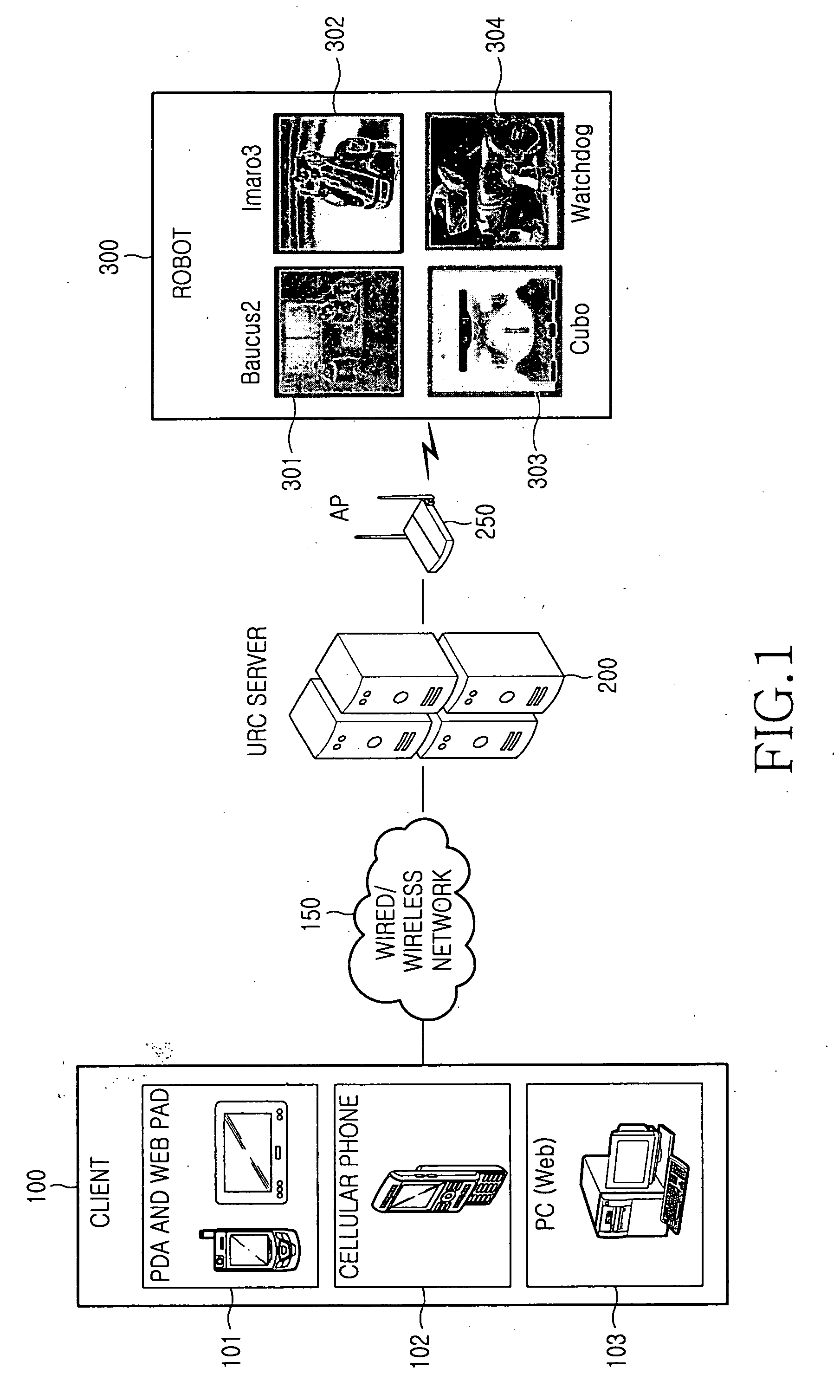
[0027]FIG. 1 illustrates a network-based robot control system according to the present invention. Referring to FIG. 1, the network-based robot control system includes a client 100, a wired / wireless network 150, a Ubiquitous Robotic Companion (URC) server 200, an Access Point (AP) 250, and a robot 300.

[0028] The client 100 may be a Personal Digital Assistant (PDA) a web pad 101, a cellular phone 102, or a wired / wireless communication terminal such as a Personal Computer (PC) 103 and connects to the URC server 200 through the ...


PUM


Abstract

Provided are a network-based robot control system and a robot velocity control method in the network-based robot control system. A client calculates a robot control velocity according to its reception state of video data frames captured by a robot, generates a robot control message including the calculated robot control velocity, and transmits the robot control message to the robot. The robot then changes its velocity according to the robot control velocity included in the received robot control message. In this way, the velocity of the robot is controlled according to the video data reception state of the client, thereby allowing a user to easily control the robot regardless of the performance of the client.

Description

PRIORITY [0001] This application claims priority under 35 U.S.C. § 119 to an application entitled “Network-Based Robot Control System and Robot Velocity Control Method in the Network-Based Robot Control System” filed in the Korean Intellectual Property Office on May 24, 2005 and assigned Serial No. 2005-43722, the entire contents of which are incorporated herein by reference. BACKGROUND OF THE INVENTION [0002] 1. Field of the Invention [0003] The present invention generally relates to a robot control system, and in particular, to a network-based robot control system such as a Ubiquitous Robotic Companion (URC) and a robot velocity control method in the network-based robot control system. [0004] 2. Description of the Related Art [0005] A mechanical apparatus which automatically makes a determination and carries out certain operations in accordance with specific instructions using sensors corresponding to human senses is referred to as a “robot”. Conventional robots are now evolving i...

Claims


Application Information

Patent Timeline
Patent Type & Authority Applications(United States)
IPC IPC(8): G06F19/00B25J13/08G05D1/00
CPCG05B2219/40174B25J9/1689B25J11/00
Inventor CHOI, BYUNG-KWONSHIM, HYUN-SIKKIM, JOON-KOO
Owner SAMSUNG ELECTRONICS CO LTD
Why Eureka
Try Eureka