

Skylight system
a skylight system and skylight technology, applied in the field of skylight systems, can solve the problems of not being able to adequately prevent ingress, not being able to prove against flying embers, and not being able to conform to the required trafficability standards of commonly available skylights of overseas manufactur
- Summary
- Abstract
- Description
- Claims
- Application Information
AI Technical Summary
Benefits of technology
Problems solved by technology
Method used
Image

Examples
first preferred embodiment
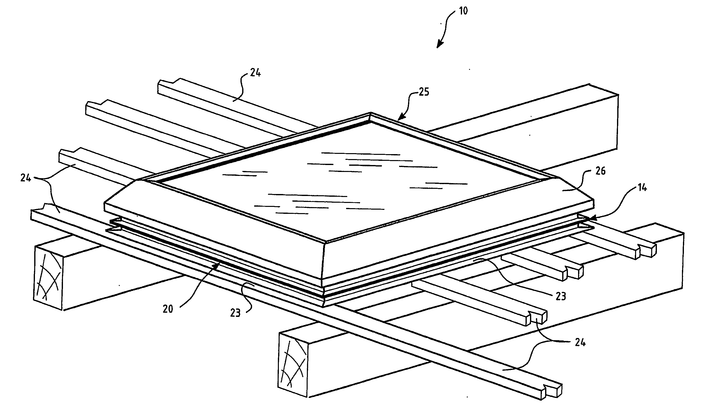
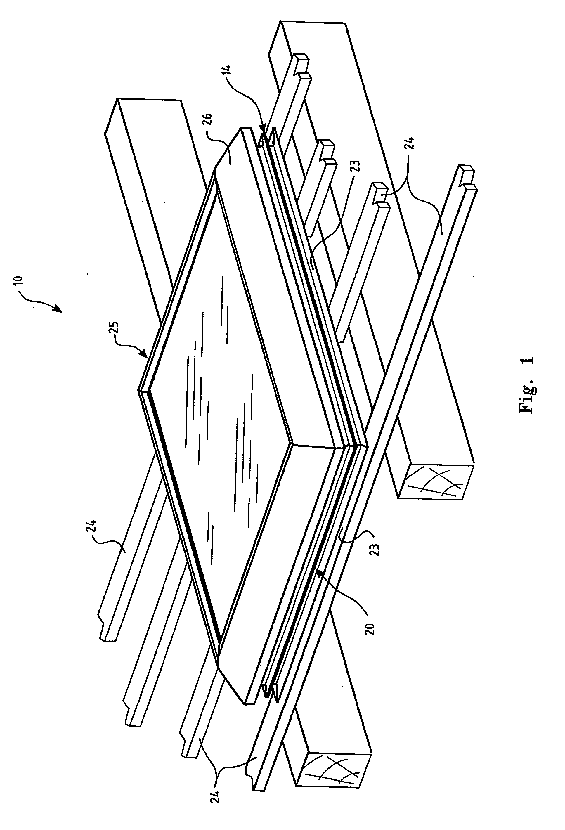
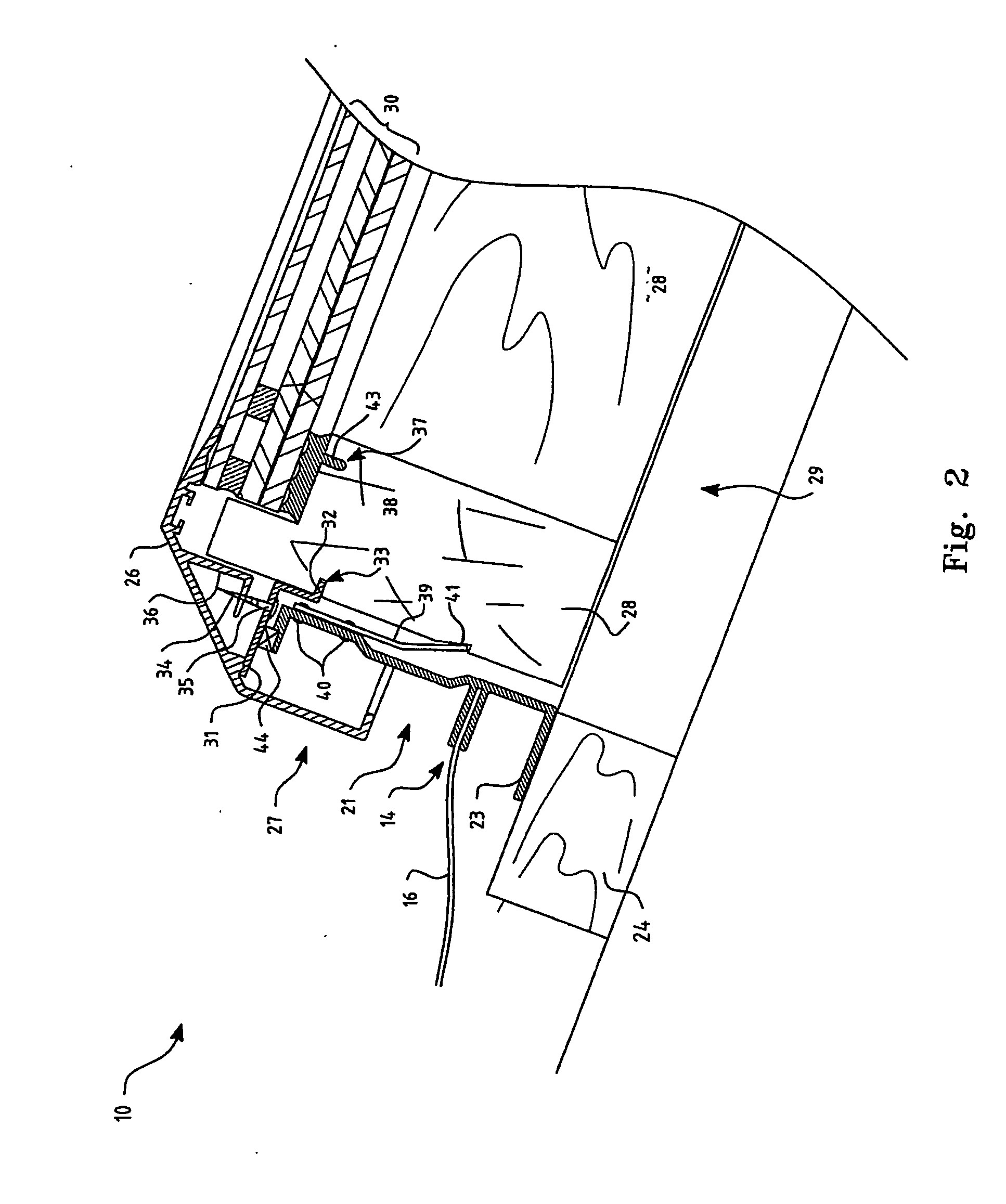
[0050] A first preferred embodiment of a skylight system 10 according to the invention will now be described with reference to FIGS. 1 to 4. A prefabricated mounting frame 20 is constructed from extruded sections 21 to form a generally rectangular support structure 22 as may best be seen in FIG. 4, and is provided with bottom flange 23 adapted to rest on the batten timbers 24 of a roof as shown in FIG. 1. The upper edge of extruded section 21 is provided with a horizontal top ledge 41 adapted to accept sealing strip 44.
[0051] Extruded section 21 is further provided with projecting flanges 14 adapted to receive flashing elements 15, 16 and 16A as shown in FIG. 4. Flashing elements 15, 16 and 16A are pre-assembled with rectangular support structure 22 by crimping flashing 15, 16 and 16A between the projecting flanges 14 so as to allow integration of the flashing with roofing material such as tiles when installing the skylight system 10.
[0052] In at least one preferred embodiment of ...
second preferred embodiment
[0066] A second preferred embodiment of a skylight system according to the invention will now be described with reference to FIGS. 5 and 6 wherein like elements of the first embodiment are similarly numbered but with the addition of 100 so that for example feature 22 of the first embodiment is referenced as feature 122 in the second embodiment.
[0067] Accordingly there is provided a rectangular support structure 122 fabricated from extruded sections 121 and provided with flange elements 123 to allow structure122 to be positioned on roof battens 124. As for the first embodiment already described, the extruded sides of structure 122 are provided with projecting flanges 114 to allow the pre-assembly of flashing (not shown) along the two sloping sides of skylight system 100 and conventional malleable flat flashing 115 along the upper and lower horizontal sides.
[0068] Extruded sections 121 in this embodiment are so formed as to allow the clip-on attachment of an extruded hinge section 1...
third preferred embodiment
[0072] A third preferred embodiment of a skylight system according to the invention will now be described with reference to FIG. 7 wherein like elements of the first and second embodiments are similarly numbered but with the addition of 200 so that for example feature 22 of the first embodiment and 122 of the second embodiment is referenced as feature 222 in this third embodiment.
[0073] Accordingly, in FIG. 7 rectangular support structure 222 is located on roof battens 224 as before resting on flange elements 223. In this embodiment prefabricated hood assembly 225 is provided with cowling 250. Cowling 250 is provided with opening 251 and hinged flap 252.
[0074] As shown in FIG. 8, hinged flap 252 is hinged by means of hinge arrangement 258 wherein extruded element 259 of cowling 250 is so formed as to provided rotational support for mating extruded element 260 of hinged flap 252.
[0075] Again with reference to FIG. 8, contained in cowling 250 is motor and fan assembly 260 where bar...
PUM
 Abstract
Description
Claims
Application Information