Pressure chamber nozzle assembly

a technology of pressure chamber and nozzle, which is applied in the direction of liquid handling, combustion types, applications, etc., can solve the problems of aerosol spray cans not being able to work, heavy and particulate materials to be dispersed have a tendency to clog up the valve assemblies, and the nozzle on occasion may clog, so as to facilitate greater compression of sprayable materials and improve shearing of materials. , the effect of increasing the pressur

Inactive Publication Date: 2006-12-07
WOODS JOHN R
View PDF6 Cites 21 Cited by
  • Summary
  • Abstract
  • Description
  • Claims
  • Application Information

AI Technical Summary

Benefits of technology

[0011] The present invention provides a valve assembly for use in an aerosol spray can which is configured to spray material with an increased pressure, an increased degree of atomization and reduced clogging over traditional valve assemblies known in the art. Such improved functionality stems from the inclusion of a pressure chamber in the dispensing assembly prior to the discharge opening. The nozzle assembly is capable of spraying a wide variety of different types of materials. Such materials include, but are not limited to, paints, resins, other liquids and viscous materials or materials with large particulates.
[0012] The nozzle assembly according to the present invention uses many of the same elements as conventional nozzle assemblies, but incorporates a pressure chamber in the exit passageway so that material exiting the container passes through the pressure chamber prior to exiting the system through the discharge opening or orifice. The inclusion of the pressure chamber as part of the exit passageway allows for pressure build-up prior to the spray material's exit of the dispensing system and generates increased shearing and atomization. The increased pressure also leads to a reduced tendency for the nozzle to clog.
[0013] In embodiments, the nozzle assembly may comprise an actuator with a graduated tip extending therefrom. For example, the actuator is configured so that the opening from which the sprayable material enters the tip is larger than the opening from which the sprayable material exits the tip. A pressure chamber is fit over the graduated tip so that the chamber and the tip are in fluid communication with one another and the sprayable material flows from the graduated tip into the pressure chamber. The opening through which the sprayable material exits the tip and enters the pressure chamber is also larger than the opening from which the sprayable material exits the pressure chamber. In embodiments, the pressure chamber is comprised of rubber and has a generally cone-shaped structure. The pressure chamber may also be composed of other elastic or malleable materials in place of rubber. A dial component is further attached over the pressure chamber by screwing threads on the graduated tip that are complementary to screwing threads on the inside of the dial component. The dial component facilitates changing the diameter of the variable discharge opening so that different sprays may be dispensed. By altering the sprays, the user can apply the material to create surface textures of variable patterns onto the desired surface.
[0015] In further embodiments, the nozzle assembly has two horizontally-aligned dials attached on the pressure chamber. As discussed above, each dial is attached to the nozzle assembly by screwing threads on the graduated tip. The user can tighten each one by turning the dial so that it screws toward the actuator and loosen each one by turning the dial so that it screws in the opposite direction—away from the actuator. One dial is used to alter how much material is allowed to enter the pressure chamber while the second dial is used to change the spray by altering the size of the variable discharge opening or orifice. The dials can operate independent of one another. This embodiment allows the user to change the pressure chamber if desired, change the variable discharge opening if desired, or change both if desired.
[0016] Embodiments of the invention subject the spray material to increased pressure prior to dispensing. The present embodiments of the pressure chamber facilitates greater compression of the sprayable material prior to exiting than previously known nozzle assemblies. This higher level of compression causes better shearing of the material so that the material is sprayed with much higher atomization. The increased pressure also leads to a reduced tendency for the nozzle to clog.

Problems solved by technology

The practice of dispensing sprayable materials through traditional aerosol spray can valve assemblies has presented problems in that the nozzle on occasion may clog, particularly when the spray can is used infrequently.
Furthermore, the practice of dispensing heavy and particulate materials through traditional aerosol spray can valve assemblies in the aerosol industry has presented problems in that the heavy and particulate materials to be dispersed have a tendency to clog up the valve assemblies.
However, because of the placement of the valve assembly in traditional aerosol spray cans, both traditional spray materials as well as the heavy and particulate materials will clog up the valve assemblies and render the aerosol spray cans inoperative.
For example, constant operation of these aerosol spray cans in spraying heavy and particulate materials is not possible due to the inconsistent ability of these traditional valve assemblies to dispense these materials without clogging.
Although the nozzle tube of the device in the '975 patent may be configured to spray texture materials, the device in the '975 patent still has the problem of clogging or packing of the valve assembly by the particulates contained in the texture material for spraying, especially if the particulates are large, like those found in stucco or other heavy and particulate materials mentioned above.

Method used


Image

  • Pressure chamber nozzle assembly
  • Pressure chamber nozzle assembly
  • Pressure chamber nozzle assembly

Examples


Embodiment Construction

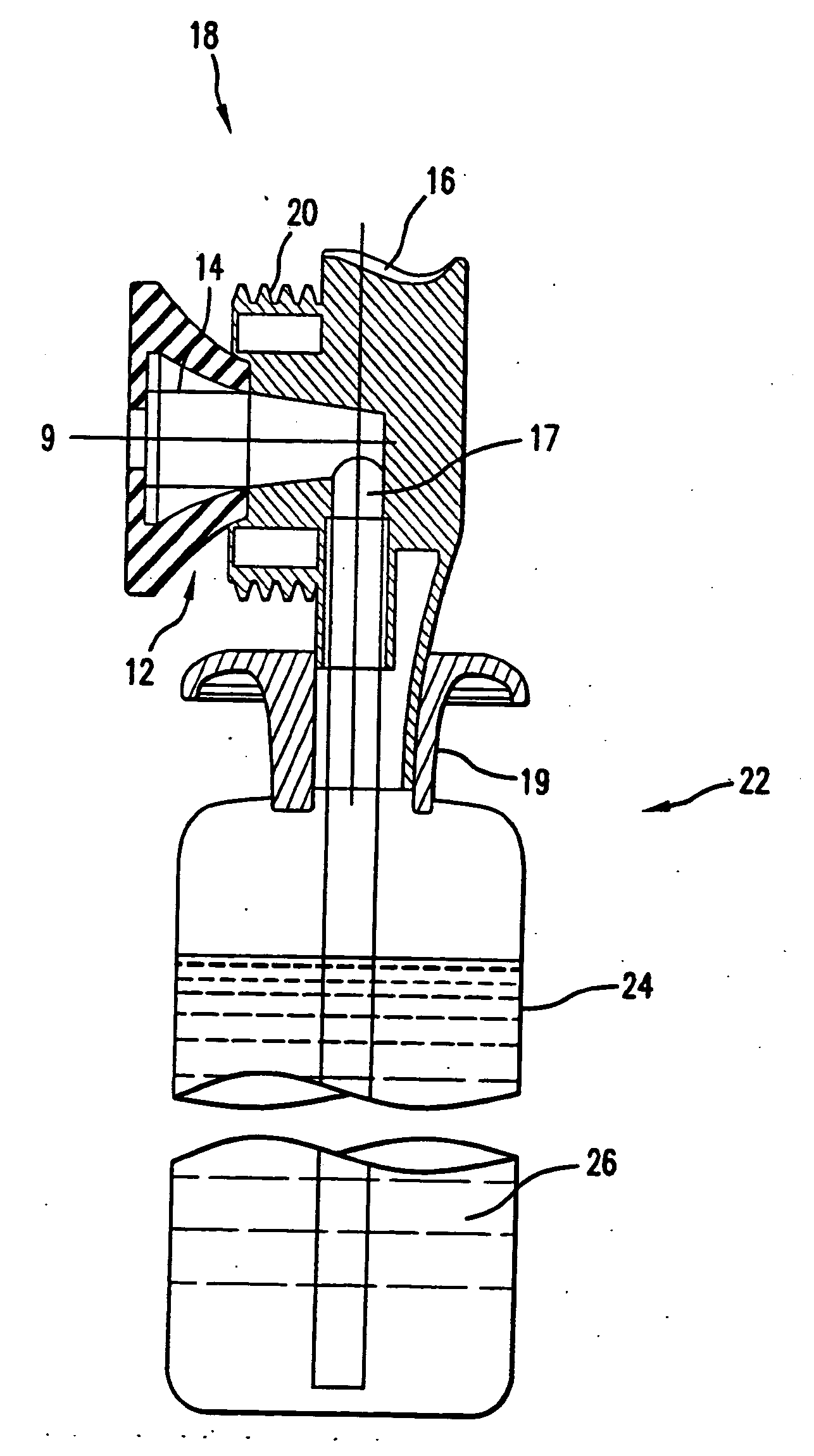
[0028] The present invention provides a valve assembly for use in an aerosol spray can which is configured to spray material with an increased pressure, an increased degree of atomization and reduced clogging over traditional valve assemblies known in the art. Such improved functionality stems from the inclusion of a pressure chamber in the dispensing assembly prior to the discharge opening. The nozzle assembly is capable of spraying a wide variety of different types of materials. Such materials include, but are not limited to, paints, resins, other liquids and viscous materials or materials with large particulates. The present invention may also be used in a wide variety of spray devices, including but not limited to, spray guns, spray hoppers, aerosol cans and canisters, and the like.

[0029] The present invention provides an inexpensive and economical means for dispensing materials with an increased degree of atomization and a reduced incidence of clogging of the nozzle. Such redu...


PUM


Abstract

A nozzle assembly is disclosed which provides for increased atomization, a finer spray, and a reduced tendency of the apparatus to clog. The nozzle assembly includes a pressure chamber through which the spray material must pass prior to exiting the spray container through a discharge orifice. As material exiting the container passes through the pressure chamber, pressure is built up, resulting in increased shearing and atomization of the spray material.

Description

CROSS-REFERENCE TO RELATED APPLICATIONS [0001] This application is a continuation-in-part of pending U.S. patent application Ser. No. 10 / 831,913, filed Apr. 26, 2004.BACKGROUND OF THE INVENTION [0002] 1. Field of the Invention [0003] This invention generally relates to a nozzle assembly for use with a spray can. More particularly, the invention relates to a nozzle assembly configured to induce additional pressure build-up so that the substance being sprayed is atomized to a higher degree, with a reduced incidence of clogging over other nozzles known in the art. [0004] 2. Description of Related Art [0005] The practice of dispensing sprayable materials through traditional aerosol spray can valve assemblies has presented problems in that the nozzle on occasion may clog, particularly when the spray can is used infrequently. Additionally, in some instances, a greater degree of atomization may be desired for optimum functioning of the spray device. Furthermore, the practice of dispensing ...

Claims


Application Information

Patent Timeline
Patent Type & Authority Applications(United States)
IPC IPC(8): B05B15/00B05B1/02B05B9/04B65D83/14B65D83/28B65D83/52B67B7/00
CPCB65D83/303
Inventor WOODS, JOHN R.
Owner WOODS JOHN R
Why Eureka
Try Eureka