Method, apparatus, and article for adjusting optical device

a technology of optical devices and adjusting devices, applied in the field of methods, can solve the problems of affecting the smooth focus of optical devices, the difficulty of affecting clockwise and counterclockwise rotation, and the disproportionate amount of time and effort required to make adjustments, etc., and achieve the effect of improving drawing legibility

Inactive Publication Date: 2006-12-07
INTERMEC IP
View PDF7 Cites 0 Cited by
  • Summary
  • Abstract
  • Description
  • Claims
  • Application Information

AI Technical Summary

Benefits of technology

[0012] In the drawings, identical reference numbers identify similar elements or acts. The sizes and relative positions of elements in the drawings are not necessarily drawn to scale. For example, the shapes of various elements and angles are not drawn to scale, and some of these elements are arbitrarily enlarged and positioned to improve drawing legibility. Further, the particular shapes of the elements as drawn, are not intended to convey any information regarding the actual shape of the particular elements, and have been solely selected for ease of recognition in the drawings.

Problems solved by technology

For example, the amount of time and effort required to make an adjustment is disproportionately high relative to the amount of adjustment actually provided.
In some situations, due to either space constraints or user limitations, it may be difficult to affect both clockwise and counterclockwise rotation with comparative ease.
And if the user rotates the screw too far in one direction while the lens is near either end of the adjustment range, the optical device loses the smooth ability to focus.
Such an arrangement may cause misalignment or unequal forces in the carriage mechanism, and / or may require adjustment of multiple screws.

Method used


Image

  • Method, apparatus, and article for adjusting optical device
  • Method, apparatus, and article for adjusting optical device
  • Method, apparatus, and article for adjusting optical device

Examples


Embodiment Construction

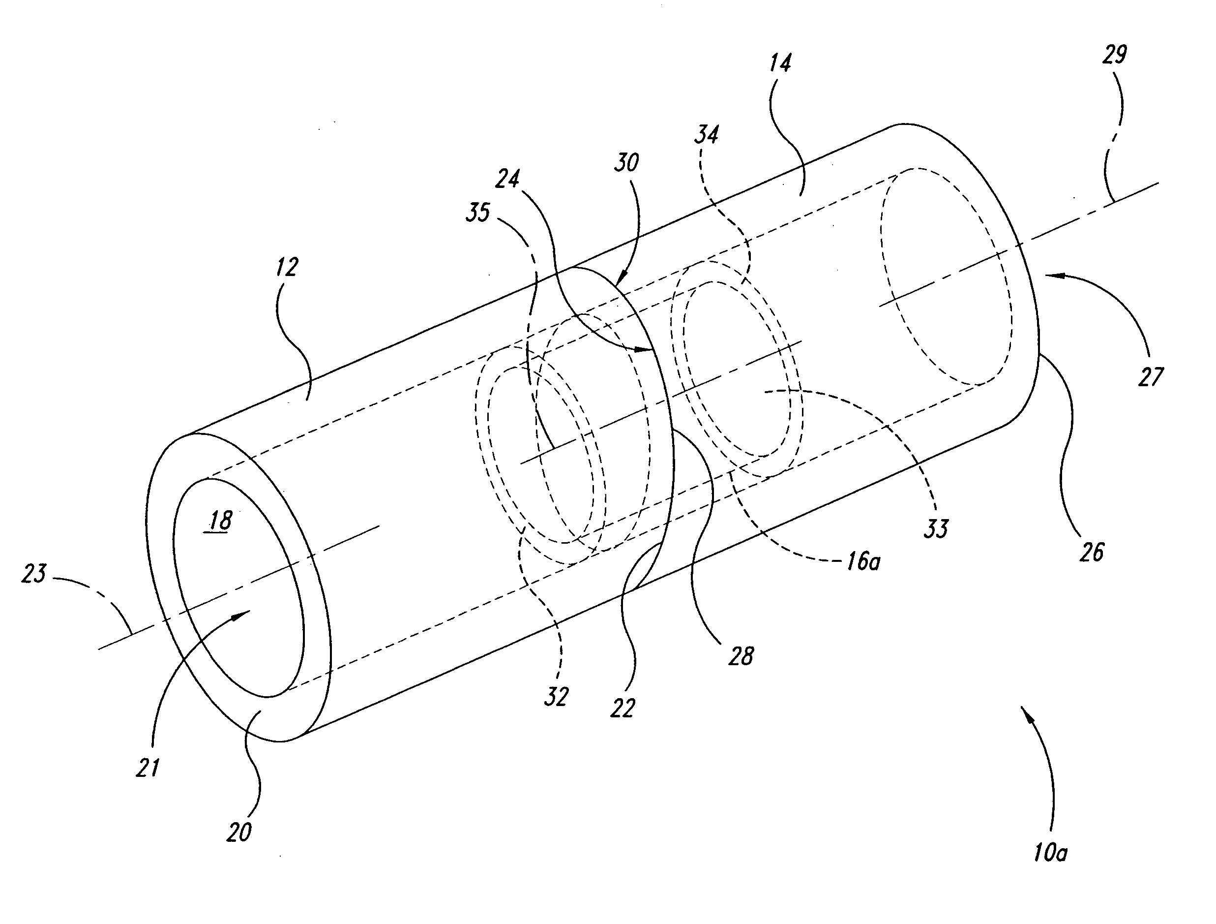
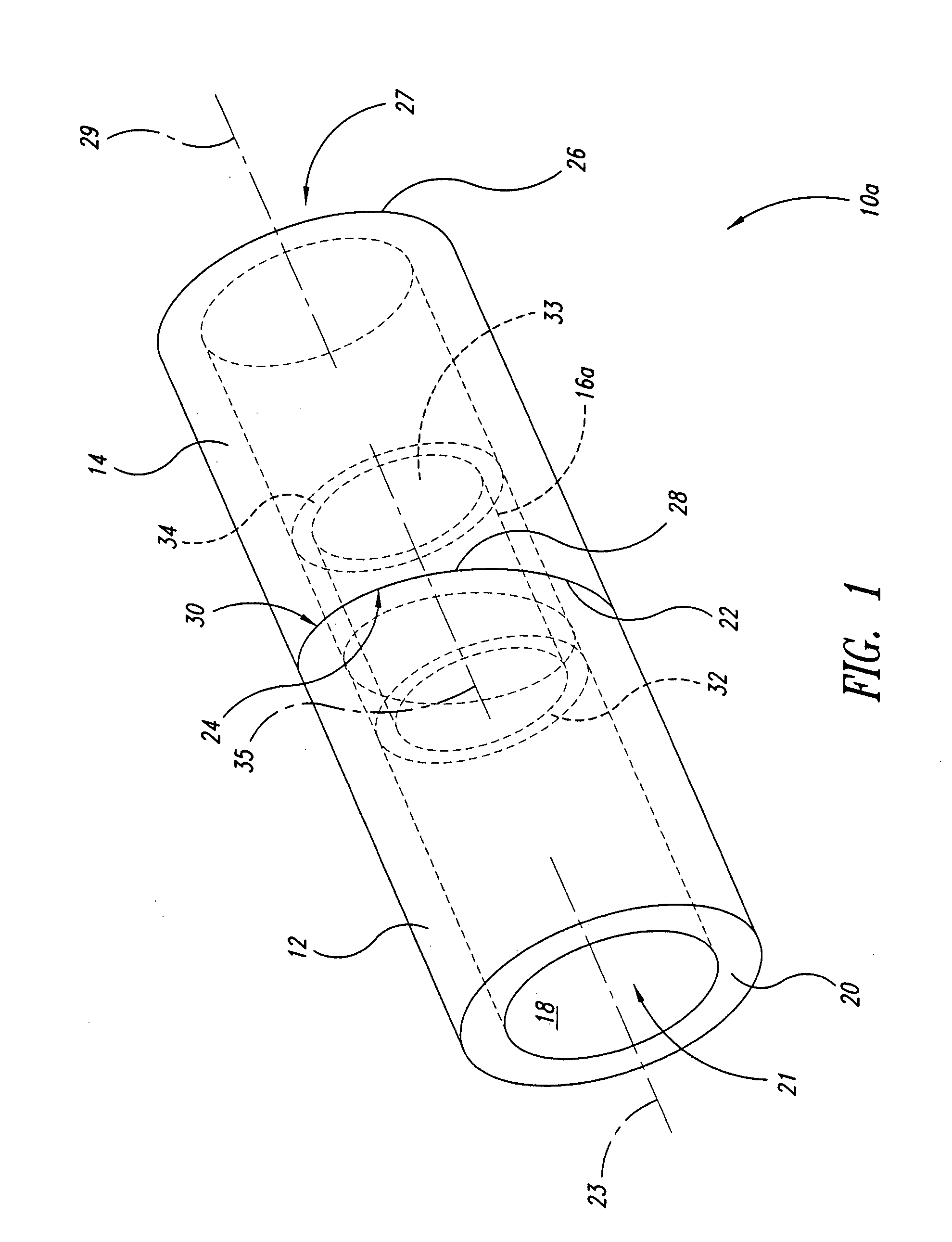
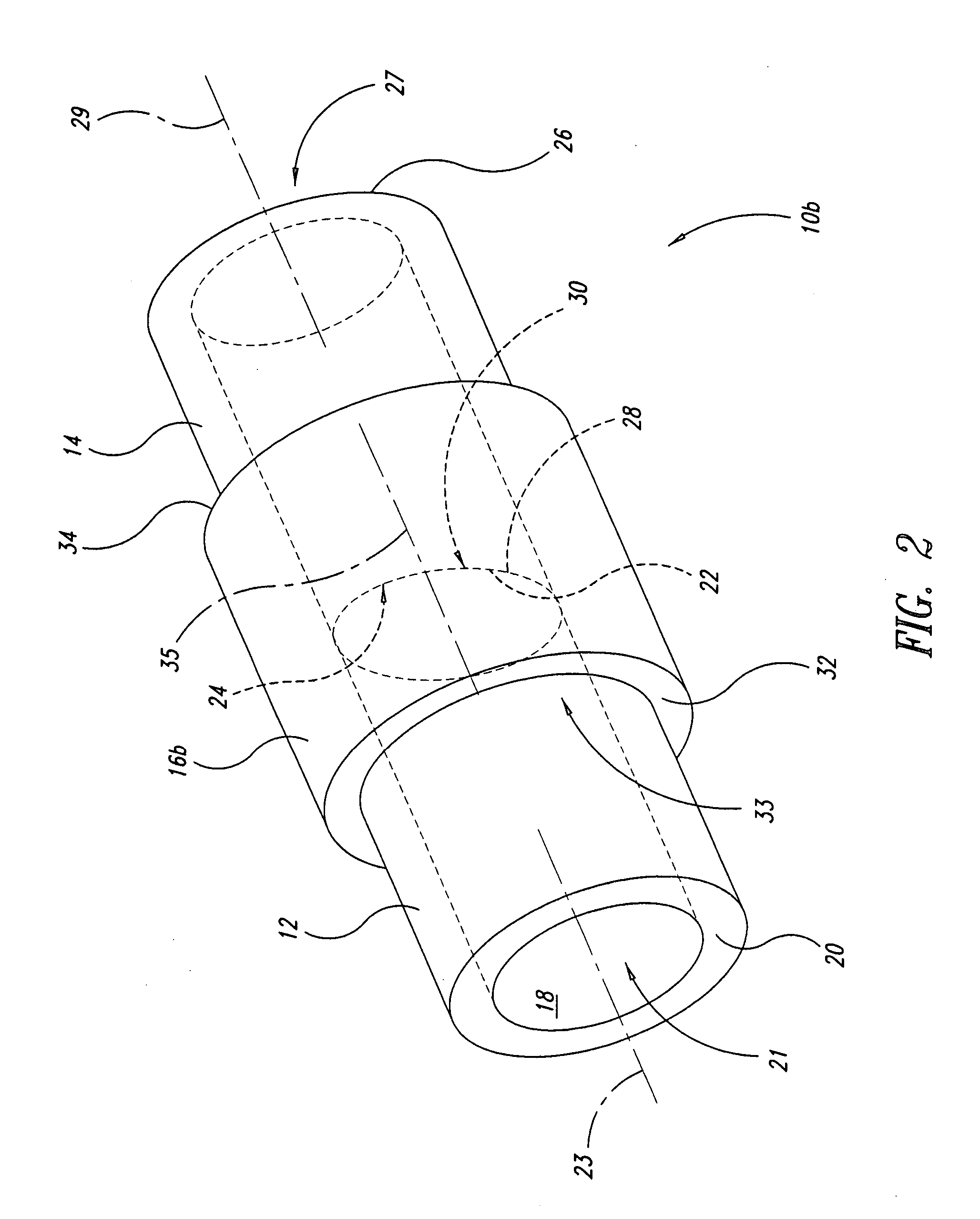
[0020] In the following description, certain specific details are set forth in order to provide a thorough understanding of various disclosed embodiments. However, one skilled in the relevant art will recognize that embodiments may be practiced without one or more of these specific details, or with other methods, components, materials, etc. In other instances, well-known structures associated with optical devices and optical elements have not been shown or described in detail to avoid unnecessarily obscuring descriptions of the embodiments.

[0021] Unless the context requires otherwise, throughout the specification and claims which follow, the word “comprise” and variations thereof, such as, “comprises” and “comprising” are to be construed in an open, inclusive sense, that is as “including, but not limited to.”

[0022] Reference throughout this specification to “one embodiment” or “an embodiment” means that a particular feature, structure or characteristic described in connection with ...


PUM


Abstract

An optical assembly includes a first tubular member having a pitched bearing surface proximate one end; a second tubular member having a pitched bearing surface proximate one end; a coupling tubular member fixedly coupled to the second tubular member and rotatably and slideably coupled to the first tubular member; and an optical element received in at least one of the first, the second or the coupling tubular members. At least a portion of the pitched bearing surface of the first tubular member is in engaging contact with at least a portion of the pitched bearing surface of the second tubular member. Rotating the first tubular member with respect to the second tubular member smoothly varies a distance between the first and second tubular members and allows a large, smooth adjustment with little effort. Rotation in a single direction returns the distances to an initial starting point.

Description

CROSS REFERENCES TO RELATED APPLICATIONS [0001] This application claims benefit under 35 U.S.C. § 119(e) from U.S. Provisional Patent Application No. 60 / 672,785, filed Apr. 19, 2005.BACKGROUND OF THE INVENTION [0002] 1. Field of the Invention [0003] The method, apparatuses, and articles described herein generally relate to optical devices, and may, for example, be useful in automatic data collection devices such as optical readers of machine-readable symbols. [0004] 2. Description of the Related Art [0005] At present, the most prevalent method of adjusting an optical device appears to employ threaded screws. However, adjusting an optical device through use of a screw has a number of disadvantages. [0006] For example, the amount of time and effort required to make an adjustment is disproportionately high relative to the amount of adjustment actually provided. Numerous repeated rotations of the screw are often necessary to achieve the desired adjustment. For example, movement of a len...

Claims


Application Information

Patent Timeline
Patent Type & Authority Applications(United States)
IPC IPC(8): A47D1/10A47C1/08
CPCG02B7/023
Inventor CABRERA, PIERREMANINE, PIERRE-MARIE
Owner INTERMEC IP
Why Eureka
Try Eureka