Machine-readable symbol reader and method employing an ultracompact light concentrator with adaptive field of view

Active Publication Date: 2009-01-15
INTERMEC IP
View PDF9 Cites 5 Cited by
  • Summary
  • Abstract
  • Description
  • Claims
  • Application Information

AI Technical Summary

Benefits of technology

[0012]In the drawings, identical reference numbers identify similar elements or acts. The sizes and relative positions of elements in the drawings are not necessarily drawn to scale. For example, the shapes of various elements and angles are not drawn to scale, and some of these elements are

Problems solved by technology

While a compound parabolic collector is efficient at rejecting unwanted light. there is no simple way to change the field of view.
Furthermore, an ideal compound parabolic collectors, or line flow concentrators, is very long.
Thus, compound parabolic colle

Method used


Image

  • Machine-readable symbol reader and method employing an ultracompact light concentrator with adaptive field of view
  • Machine-readable symbol reader and method employing an ultracompact light concentrator with adaptive field of view
  • Machine-readable symbol reader and method employing an ultracompact light concentrator with adaptive field of view

Examples


Example

[0020]In the following description, certain specific details are set forth in order to provide a thorough understanding of various disclosed embodiments. However, one skilled in the relevant art will recognize that embodiments may be practiced without one or more of these specific details, or with other methods, components, materials, etc. In other instances, well known structures associated with optoelectronic readers such as barcode readers and methods for reading machine-readable symbols such as barcode symbols, area or matrix code symbols and / or stacked code symbols have not been shown or described in detail to avoid unnecessarily obscuring descriptions of the embodiments.

[0021]Unless the context requires otherwise, throughout the specification and claims which follow, the word “comprise” and variations thereof, such as, “comprises” and “comprising” are to be construed in an open, inclusive sense, that is as “including, but not limited to.”

[0022]Reference throughout this specifi...


PUM


Abstract

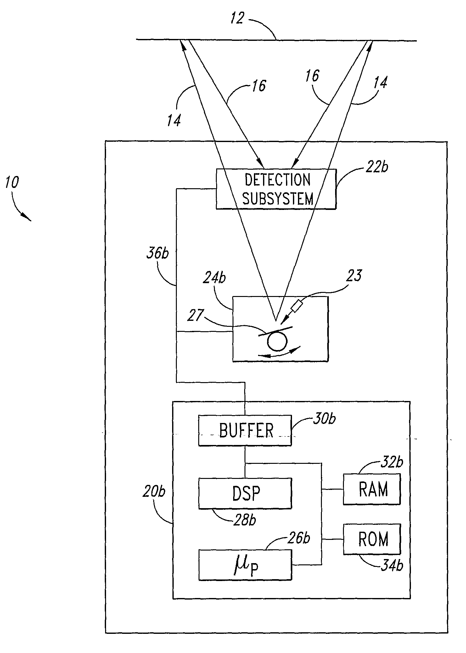
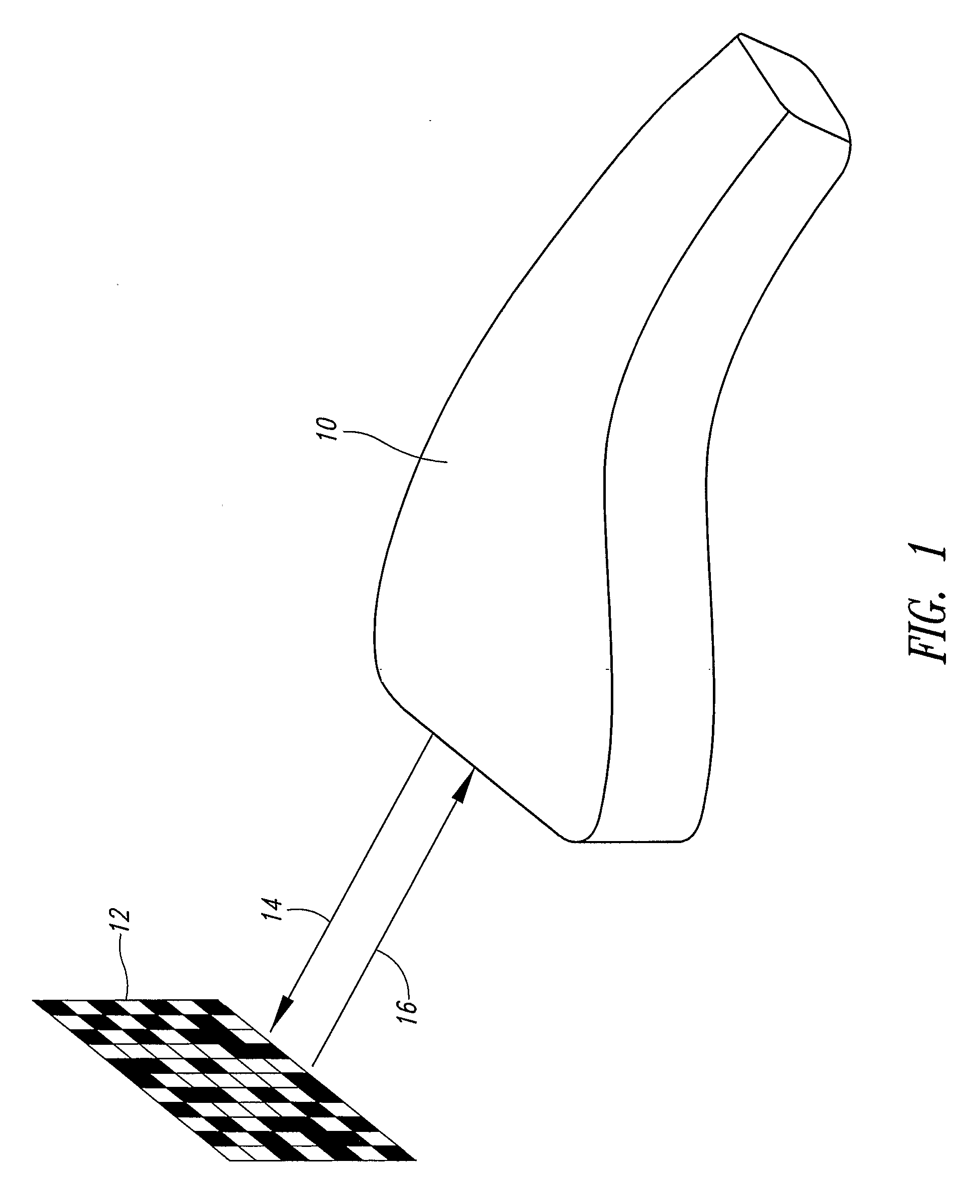
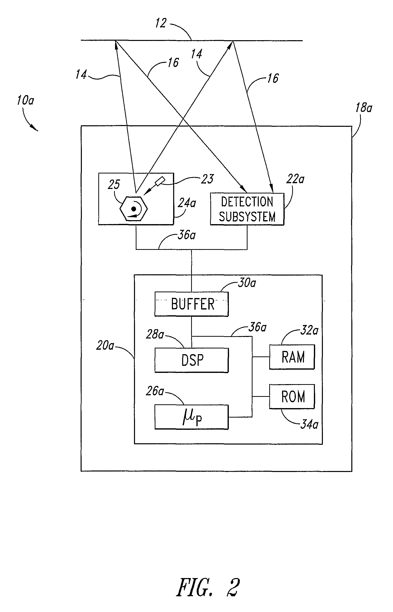
An optoelectronic reader for reading machine-readable symbol such as barcode symbols employs a detection sub-system having an RX concentrator. The detection subsystem may include an N-tuple RX concentrator. The RX concentrator may define an optical path for light to illuminate the machine-readable symbol.

Description

BACKGROUND OF THE INVENTION[0001]1. Field of the Invention[0002]This disclosure generally relates to automatic data collection (ADC) devices, for example, machine-readable symbol readers such as barcode scanners.[0003]2. Description of the Related Art[0004]Readers for reading machine-readable symbols are generally categorized into two groups: 1) moving beam devices commonly referred to as scanners (e.g., laser scanners), and 2) fixed beam devices commonly referred to as imagers (e.g., CCD imagers). Each group has its own relative advantages.[0005]Moving beam devices typically move or scan a light across a target. For example, a scanner may employ a laser diode and a mechanism for moving a laser beam produced by the laser diode across the target. While it may be possible to move the light source itself, scanners typically employ one or more rotating prisms or oscillating mirrors that reflect the laser beam, sweeping the laser beam back and forth across a target, and thereby sequentia...

Claims


Application Information

Patent Timeline
IPC IPC(8): G06K7/10
CPCG06K7/10613G06K7/10702G06K7/10633
Inventor GILLET, ALAINMASSIEU, JEAN-LOUIS
Owner INTERMEC IP
Why Eureka
Try Eureka