Gas chromatograph and mass spectrometer

Inactive Publication Date: 2006-01-19
O I CORP
View PDF2 Cites 12 Cited by
  • Summary
  • Abstract
  • Description
  • Claims
  • Application Information

AI Technical Summary

Benefits of technology

[0047] In the drawings, identical reference numbers identify similar elements or acts. The sizes and relative positions of elements in the drawings are not necessarily drawn to scale. For example, the shapes of various elements and angles are not drawn to scale, and some of these elements are

Problems solved by technology

The EOID, although highly advantageous in many ways, is relatively complicated since it requires multiple conversions.
In addition, there may be complications from the use of phosphors, which may limit the dynamic range of the detector.
The micro-channel device may also be complicated, since it may require a high-voltage, for example 1 KV, to be applied.
Additionally, fringe magnetic fields may affect the electron trajectory.
The resolution of the mass analyzer may therefore be compromised due to these and other effects.
A smaller bore of the capillary tube causes narrower peaks of the effluent to be even more narrow, which is indicative of a large loss of signal.
There are many problems associated with traditional combined GC / MS instruments, due mainly to the fact that the gas chromatograph and the mass spectrometer are separate units.
The separate units have separate power supplies, separate, input / output devices, as well as other components, making them heavier and cumbersome.
In addition, the analyte has to be transferred from the gas chromatograph to the mass spectrometer, necessitating special handling of the capillary tube, which is very sensitive, and therefore difficult to connect between the two separate instruments.

Method used


Image

  • Gas chromatograph and mass spectrometer
  • Gas chromatograph and mass spectrometer
  • Gas chromatograph and mass spectrometer

Examples


Embodiment Construction

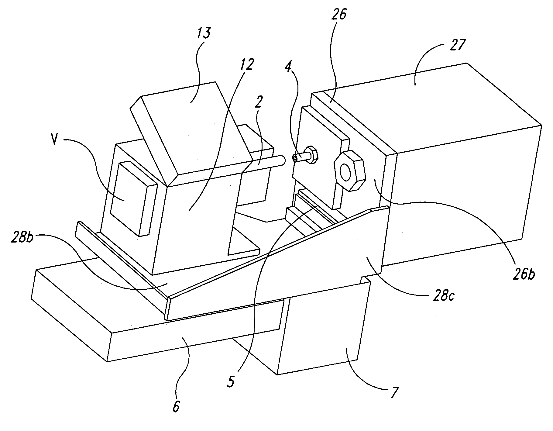
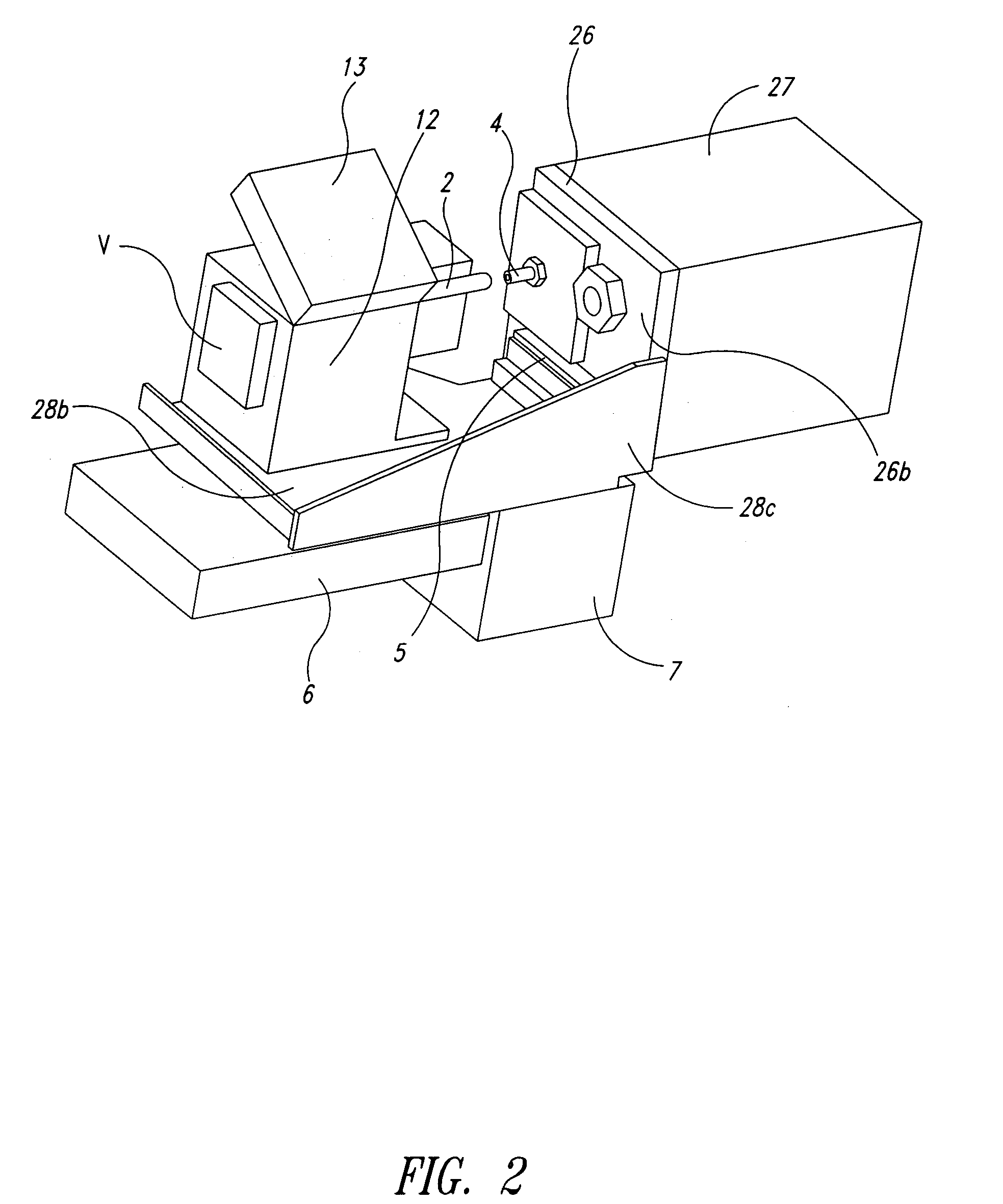
[0051] As aforementioned, the illustrated embodiments are related to integral assemblies of GS / MC instruments.

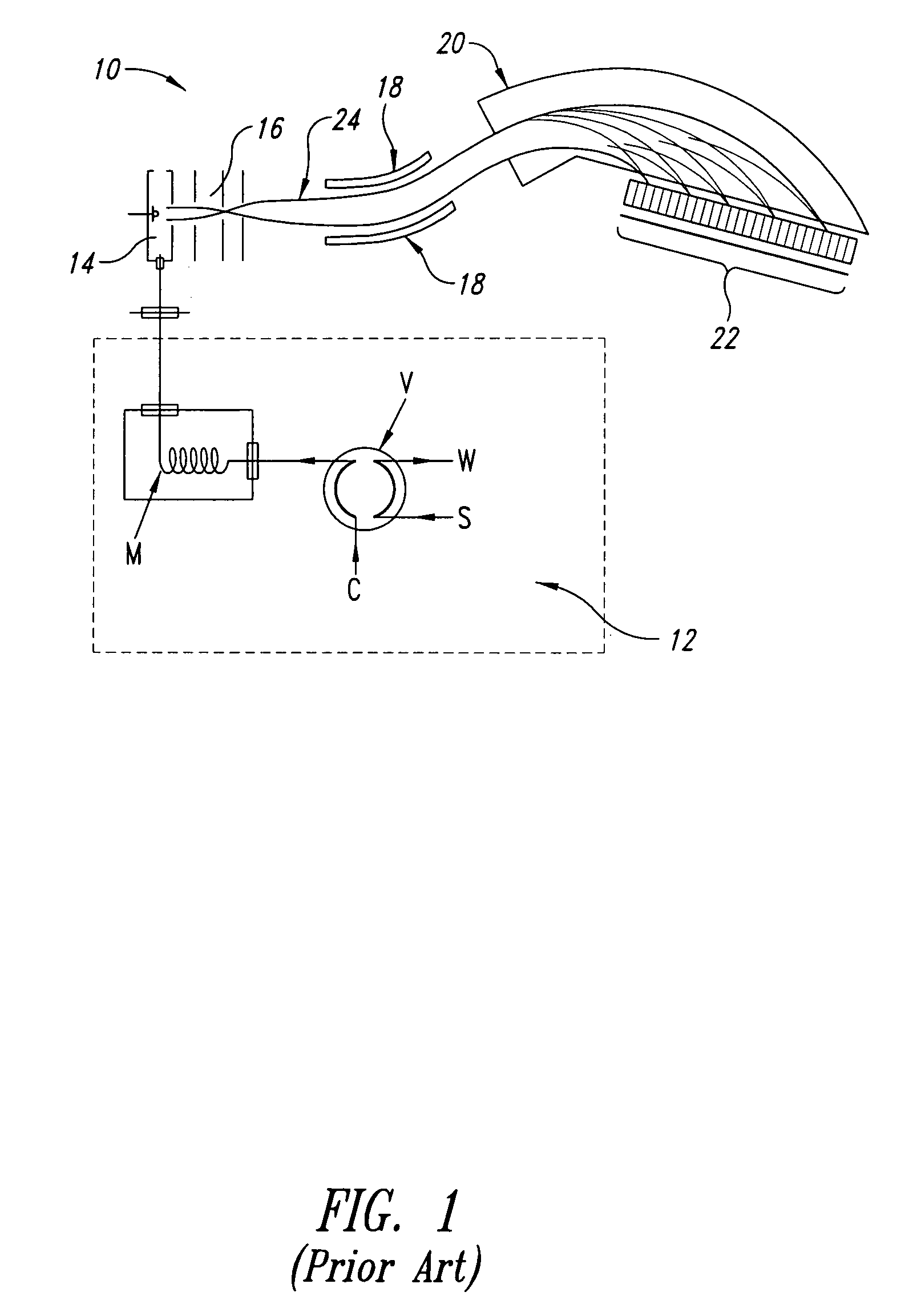
[0052] In the following description, certain specific details are set forth in order to provide a thorough understanding of various embodiments of the invention. However, one skilled in the art will understand that the invention may be practiced without these details. In other instances, well-known structures associated with gas chromatograph and mass spectrometer assemblies, such as those described above and / or referenced herein, have not necessarily been illustrated or described in detail to avoid unnecessarily obscuring descriptions of the embodiments of the invention.

[0053] Unless the context requires otherwise, throughout the specification and claims which follow, the word “comprise” and variations thereof, such as, “comprises” and “comprising” are to be construed in an open, inclusive sense, that is as “including, but not limited to.”

[0054] The terms “integral,”“inte...


PUM


Abstract

An integral gas chromatograph / mass spectrometer system is assembled by attaching a gas chromatograph assembly on one side and a mass spectrometer assembly on the other side of a master flange. The gas chromatograph assembly is accurately positioned on a holder board integrally connected to the master flange. The mass spectrometry assembly is accurately positioned on a base plate that is integrally connected to the master flange.

Description

CROSS-REFERENCES TO RELATED APPLICATION(S) [0001] This application claims the benefit of U.S. Provisional Patent Application No. 60 / 557,920 filed on Mar. 31, 2004; U.S. Provisional Patent Application No. 60 / 557,969 filed on Mar. 31, 2004; U.S. Provisional Patent Application No. 60 / 550,663 filed on Mar. 5, 2004; and U.S. Provisional Patent Application No. 60 / 550,664 filed on Mar. 5, 2004 where these four provisional applications are incorporated herein by reference in their entireties.BACKGROUND OF THE INVENTION [0002] 1. Field of the Invention [0003] This disclosure generally relates to analytic instruments, and more particularly relates to gas chromatographs, and mass spectrometers and / or mass spectrographs. [0004] 2. Description of the Related Art [0005] Mass spectrometry is widely used in many applications ranging from process monitoring to life sciences. Over the course of the last 60 years, a wide variety of instruments have been developed. The focus of new developments has bee...

Claims


Application Information

Patent Timeline
IPC IPC(8): H01J49/00G01N30/72H01J49/04H01J49/32H01J49/48
CPCG01N30/7206H01J49/025H01J49/48H01J49/322H01J49/04
Inventor SCHEIDEMANN, ADI A.KIBELKA, GOTTFRIED P.LONG, CLARE R.
Owner O I CORP
Why Eureka
Try Eureka