Dipole antenna array

a dipole antenna and array technology, applied in the field of dipole antennas, can solve the problems of undesirable diffraction effects, high cost, and high cost of ground planes, and achieve the effect of reducing the number of dipole elements

Active Publication Date: 2006-12-07
COMMSCOPE TECH LLC
View PDF18 Cites 52 Cited by
  • Summary
  • Abstract
  • Description
  • Claims
  • Application Information

AI Technical Summary

Problems solved by technology

However, the optimum value of downtilt is not always predictable prior to actual installation and testing.
A first problem with the arrangement of U.S. Pat. No. 6,924,776 is that the ground planes are expensive, bulky and heavy.
A second problem is that the edges of the steps in the ground plane can cause undesirable diffraction effects.

Method used


Image

  • Dipole antenna array
  • Dipole antenna array
  • Dipole antenna array

Examples


Embodiment Construction

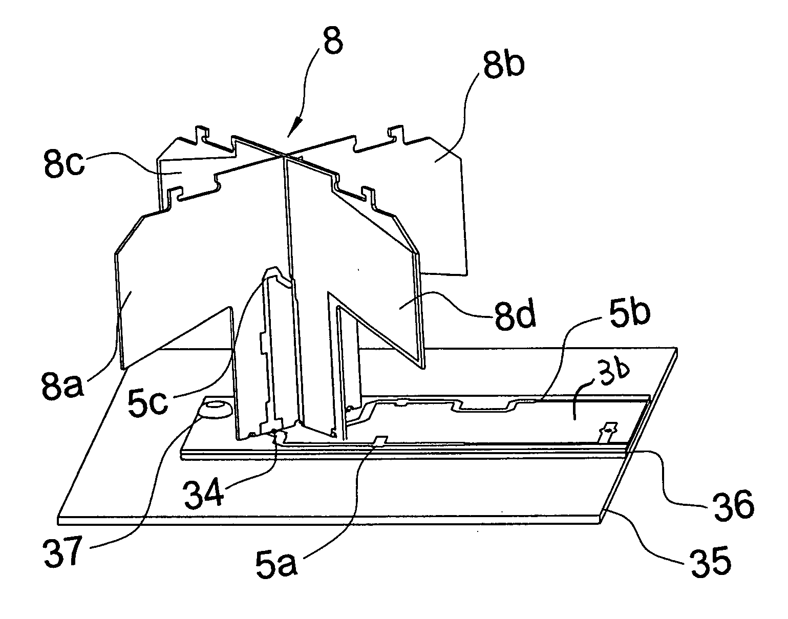
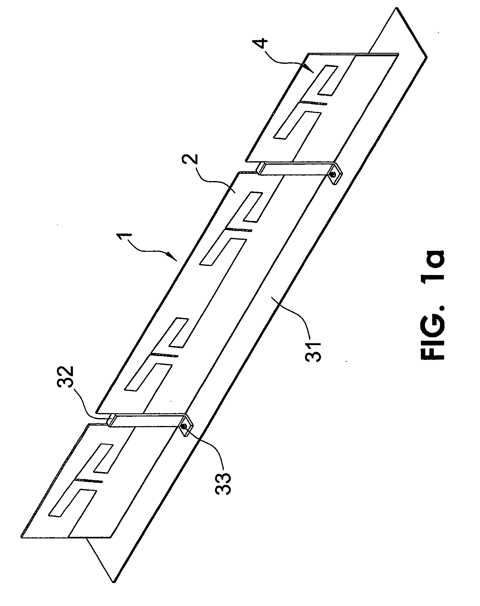
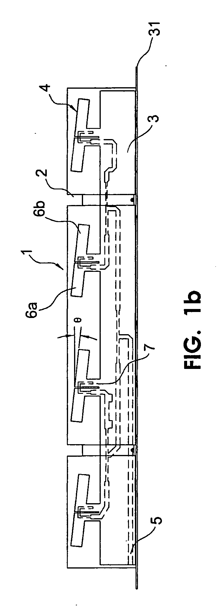
[0005] The exemplary embodiments of the invention each provide an antenna comprising a reflective surface; and an array of dipole antenna element disposed adjacent to the reflective surface, wherein each antenna element has a pair of arms which together define a dipole axis, and wherein the dipole axis is tilted at an acute angle with respect to the reflective surface.

[0006] Certain exemplary embodiments of the invention also provide an antenna element comprising a feed portion defining a feed axis; and a pair of arms which together define a dipole axis, wherein the dipole axis is tilted at an acute angle with respect to the feed axis.

[0007] Certain exemplary embodiments of the invention provide an antenna element comprising a feed portion defining a feed axis; and a dipole portion comprising a pair of arms, wherein the feed portion has a mounting portion which is tilted at an acute angle with respect to the feed axis.

BRIEF DESCRIPTION OF THE DRAWINGS

[0008] The accompanying drawi...


PUM


Abstract

An antenna comprising a reflective surface; and an array of dipole antenna elements disposed adjacent to the reflective surface. Each antenna element has a pair of arms which together define a dipole axis, and the dipole axis is tilted at an acute angle with respect to the reflective surface. The pair of arms may be dipole arms, or may be Yagi director arms. In some embodiments the dipole axis is tilted at an acute angle with respect to a feed axis. In some embodiments the antenna element comprises a feed portion defining a feed axis; and the feed portion has a mounting portion which is tilted at an acute angle with respect to the feed axis.

Description

FIELD OF THE INVENTION [0001] The present invention is related to the field of dipole antennas, and more particularly relates to an antenna with an array of dipole elements, an antenna element for use in such an antenna, and a method of operating such an antenna. BACKGROUND OF THE INVENTION [0002] Cellular communication systems employ a plurality of antenna systems, each serving a sector or area commonly referred to as a cell. The collective cells make up the total service area for a particular wireless communication network. [0003] Serving each cell is an antenna and associated switches connecting the cell into the overall communication network. Typically, the antenna system is divided into sectors, where each antenna serves a respective sector. For instance, three antennas of an antenna system may serve three sectors, each having a range of coverage of about 120°. These antennas typically have some degree of downtilt such that the beam of the antenna is directed slightly downwardl...

Claims


Application Information

Patent Timeline
Patent Type & Authority Applications(United States)
IPC IPC(8): H01P1/18
CPCH01P1/184H01Q21/26H01Q1/246H01Q3/36H01Q9/16H01Q9/285H01Q19/30H01Q21/08
Inventor TIMOFEEV, IGOR E.BRADLEY, EDDIE RAYCHAU, KY Q.ZIMMERMAN, MARTIN L.
Owner COMMSCOPE TECH LLC
Why Eureka
Try Eureka