Method of storing control information in a large-page flash memory device

a control information and flash memory technology, applied in the field of flash memory, can solve the problems of not being able to erase a previously written area of the memory without a prior erase, and the flash device has certain limitations, so as to achieve the effect of sufficient storage spa

Inactive Publication Date: 2006-12-07
SANDISK IL
View PDF11 Cites 19 Cited by
  • Summary
  • Abstract
  • Description
  • Claims
  • Application Information

AI Technical Summary

Benefits of technology

[0035] According to the present invention there is provided a method of managing storage of user data in a memory, including the steps of: (a) providing the memory with at least one unit having at least one page with sufficient storage space to store both a plurality of sectors of the user data and overhead data related to the sectors; and (b) for at least one page, partitioning the storage space among: (i) for each sector, a corresponding user data area, and (ii) at least one unit field area, each unit field area including at least one unit field, for at least one unit field there being, in the partitioned storage space, fewer instances of the one unit field than the user data areas.

Problems solved by technology

However, flash devices have certain limitations that make using them at the physical address level a bit of a problem.
In a flash device, it is not practical to rewrite a previously written area of the memory without a prior erase of the area, i.e. flash cells must be erased (e.g. programmed to “one”) before they can be programmed again.
Furthermore, some of the blocks of the device are “bad blocks” that are not reliable so that their use should be avoided.
The latter term is a misnomer, as the implementations do not necessarily support “files”, in the sense that files are used in operating systems of personal computers, but rather support block device interfaces similar to those exported by hard disk software drivers.
Even if the flash management system performs its address mappings using translation tables fully kept in RAM, it would still need to store some control information in non-volatile storage, as otherwise the flash management system would not be able to create and initialize its tables when starting up again after a power-down.
The amount of extra area available for control information is limited.
But in this case only 8 bytes are left for supporting the management algorithms, and this might result in more complex and possibly less efficient management algorithms.
Even though it would thus seem advantageous to have flash devices with a larger extra area, flash manufacturers do not generally follow this path because a larger extra area means a more expensive device.

Method used


Image

  • Method of storing control information in a large-page flash memory device
  • Method of storing control information in a large-page flash memory device
  • Method of storing control information in a large-page flash memory device

Examples


first embodiment

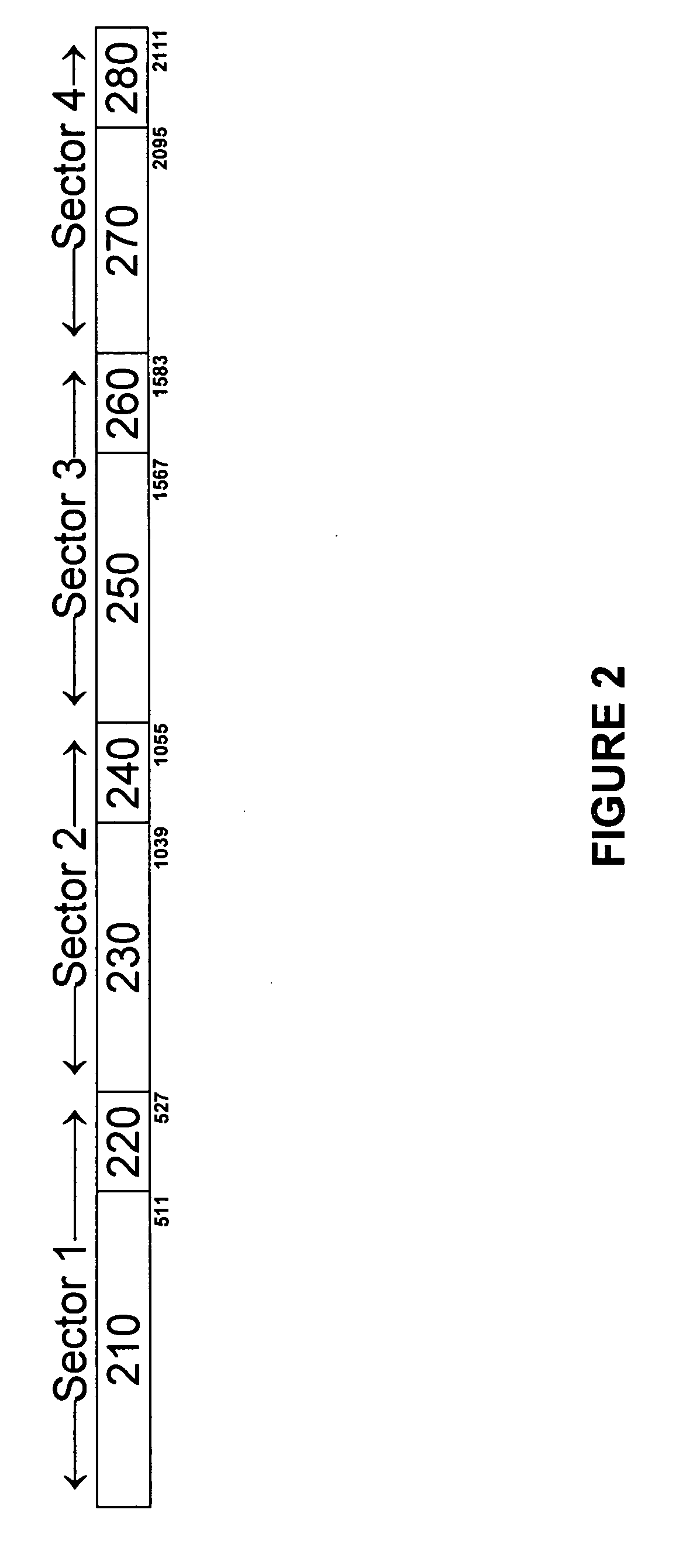
[0067] the present invention is illustrated in FIG. 5. Here, space for the unit fields is not associated with any specific sector but with the page as a whole. However, for every sector, the user data, the ECC and the page fields are grouped together and are adjacent to each other. Even though the page size in FIG. 5 is exactly the same as the page size in FIG. 2 and in FIG. 3 (in all cases 2112 bytes), the sizes of the fields that can be stored within the page is larger. Each of the four sets of ECC fields in FIG. 5 is 10 bytes long, compared to 6 bytes in FIG. 4, which provides the fields' sizes for FIGS. 2 and 3. Each of the four sets of page fields in FIG. 5 is 4 bytes long, compared to 2 bytes in FIG. 4. There are 8 bytes of unit fields in FIG. 5, the same as in FIG. 4.

[0068] It is thus possible to get both better reliability (larger ECC) and better flash management (larger page fields) while still using the same flash memories as used in prior art systems.

second embodiment

[0069] the present invention is illustrated in FIG. 6. Here not only the unit fields are not adjacent to the sectors' data, but also the page fields are not adjacent to their respective sectors but are grouped together at the beginning of the page, following the unit fields. Only the ECC bytes remain adjacent to their corresponding sectors. The sizes of fields in this embodiment is exactly the same as in the embodiment of FIG. 5, in spite of the different structure. Each set of ECC fields is 10 bytes long, each set of page fields is 4 bytes long, and the unit fields are 8 bytes long. This points out the fact it is not the relative order of the various fields that counts, and different orders can provide exactly the same field sizes and therefore exactly the same advantages.

third embodiment

[0070] the present invention is illustrated in FIG. 7. Here no control fields are put adjacent to their sector's data. Both the page fields and the ECC fields immediately follow the unit fields. Again, the end result is the same as in the previous embodiments—larger ECC and larger page fields compared to prior art systems using the same memory devices.

[0071] Many other arrangements are also possible—the unit fields may be larger than in prior art systems (unlike in all the above embodiments), the control fields may follow the sectors data, the control fields may be scattered in a few locations within the page, etc. There is absolutely no importance to the exact location of the individual fields or data sectors within the page. What counts is only the number of bytes allocated to the various types of control fields. The advantages of the present invention are not the result of any specific structure, but of the fact that space wasted in prior art systems is put to good use in this in...


PUM


Abstract

A memory for storing user data includes one or more units. Each unit has one or more pages, each with sufficient storage space for storing both several sectors of user data and related overhead data. The storage space of at least one page per unit is partitioned among user data areas (one per sector) and one or more unit field areas. Each unit field area includes at least one unit field, and the storage space includes fewer of at least one of the unit fields than there are sectors. When unit data are stored in the unit field area, there are fewer instances of at least one unit datum than there are sectors. The storage space also includes one sector field area per sector and one sector data field area per sector, and the size of the storage space is less than the sum of the area sizes times the number of sectors.

Description

[0001] This patent application claims the benefit of U.S. Provisional Patent Application No. 60 / 686,012, filed Jun. 1, 2005FIELD AND BACKGROUND OF THE INVENTION [0002] The present invention relates to flash memories and, more particularly, to a method of improving the performance of a flash memory in which multiple sectors of data are stored per page. [0003] Flash devices are electrically erasable and programmable read-only memories (EEPROMs) made of flash-type, floating-gate transistors and are non-volatile memories similar in function and performance to EPROM memories, with an additional function that allows an in-circuit, programmable operation to erase portions of the memory. Flash devices have the advantage of being relatively inexpensive and requiring relatively little power as compared to traditional magnetic storage disks. However, flash devices have certain limitations that make using them at the physical address level a bit of a problem. In a flash device, it is not practi...

Claims


Application Information

Patent Timeline
Patent Type & Authority Applications(United States)
IPC IPC(8): G06F12/00
CPCG06F2212/7207G06F12/0246
Inventor PALEY, ALEXANDERLASSER, MENAHEM
Owner SANDISK IL
Why Eureka
Try Eureka