
Partition panel assembly

a technology of partition panel and assembly, which is applied in the direction of wing accessories, door/window fittings, wing arrangement, etc., can solve the problems of complex designs that include many parts, complicated designs that require skilled personnel to install, and high manufacturing costs, so as to reduce the number of parts and reduce the skill required for installation. , the effect of reducing the speed of the door member

Inactive Publication Date: 2006-12-14
STEELCASE INC
View PDF55 Cites 37 Cited by
  • Summary
  • Abstract
  • Description
  • Claims
  • Application Information

AI Technical Summary

Benefits of technology

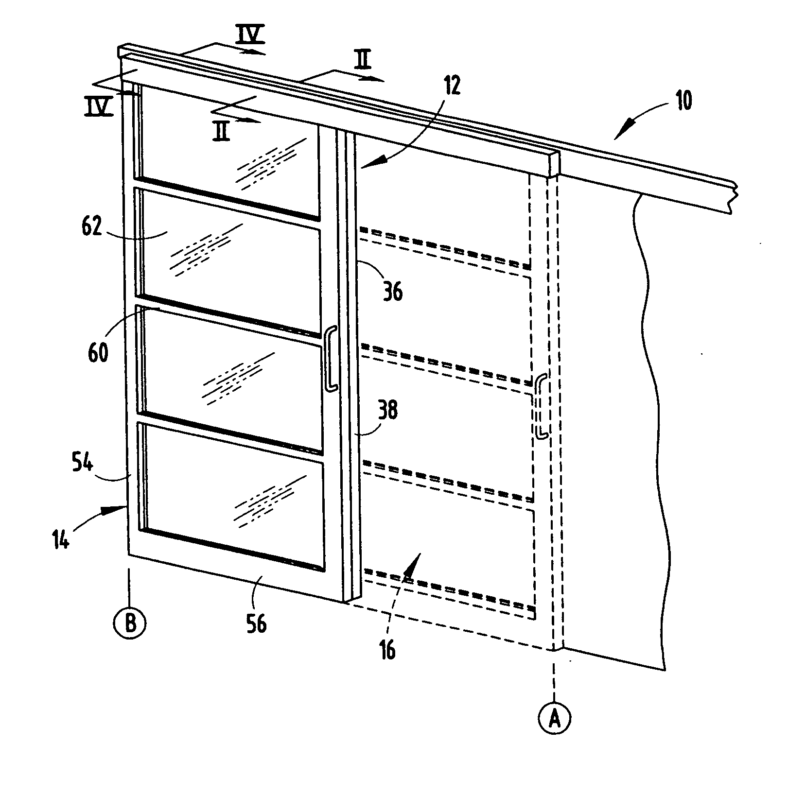
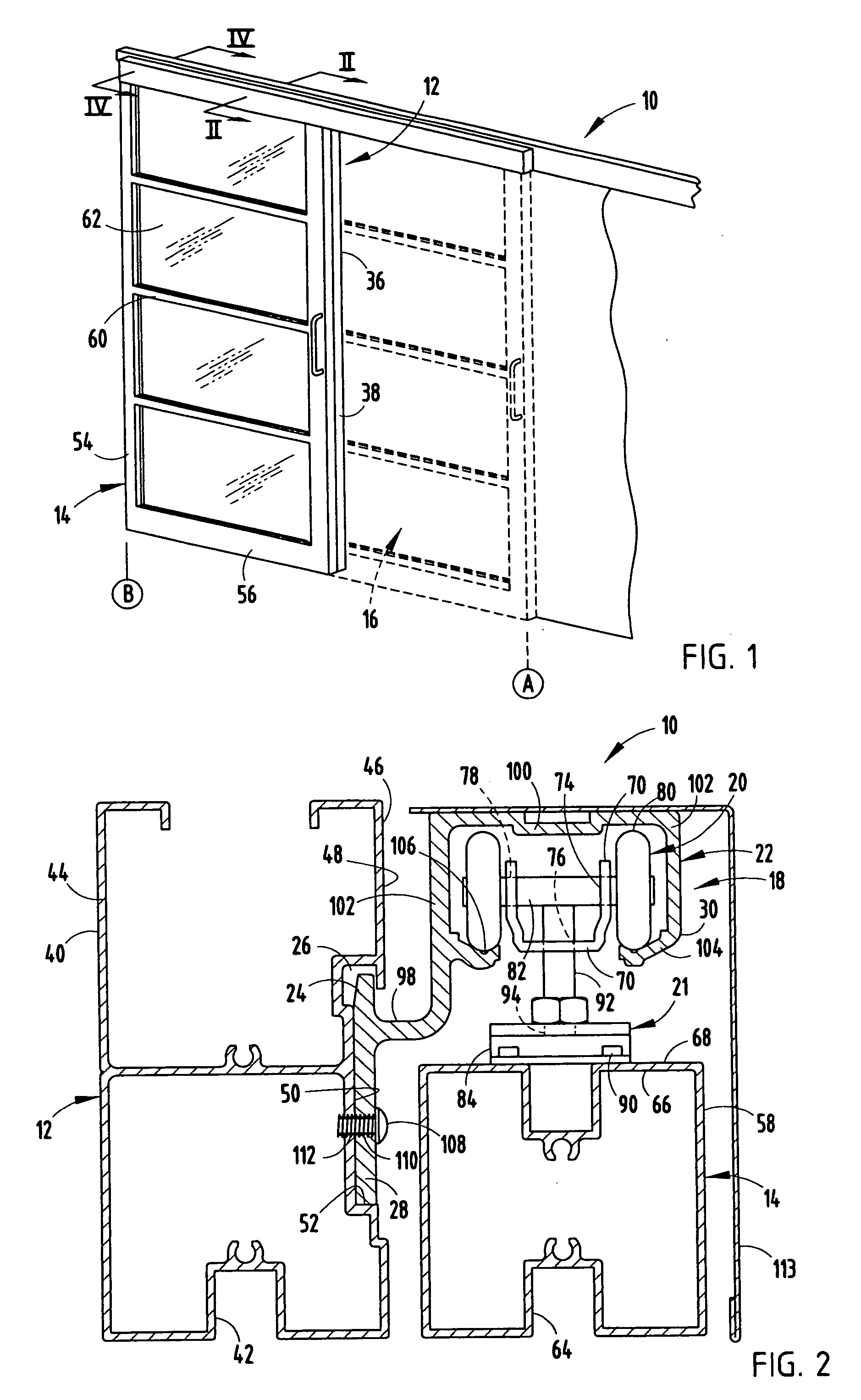
[0007] Yet another aspect of the present invention is to provide a partition panel assembly that comprises a stationary panel member, a door member having an exposed surface, and a track member supported by the stationary panel member. The partition panel assembly also includes a support assembly slidably supporting the door member from the track member between a fully-open position and a fully-closed position. The partition panel assembly further includes a decelerator assembly including a spring member secured to the track member and adapted to frictionally engage the exposed surface of the door member when the door member is proximate a select one of the fully-open position and the fully-closed position, thereby decreasing a velocity of the door member prior to the door member reaching the select one of the fully-open position and the fully-closed position.
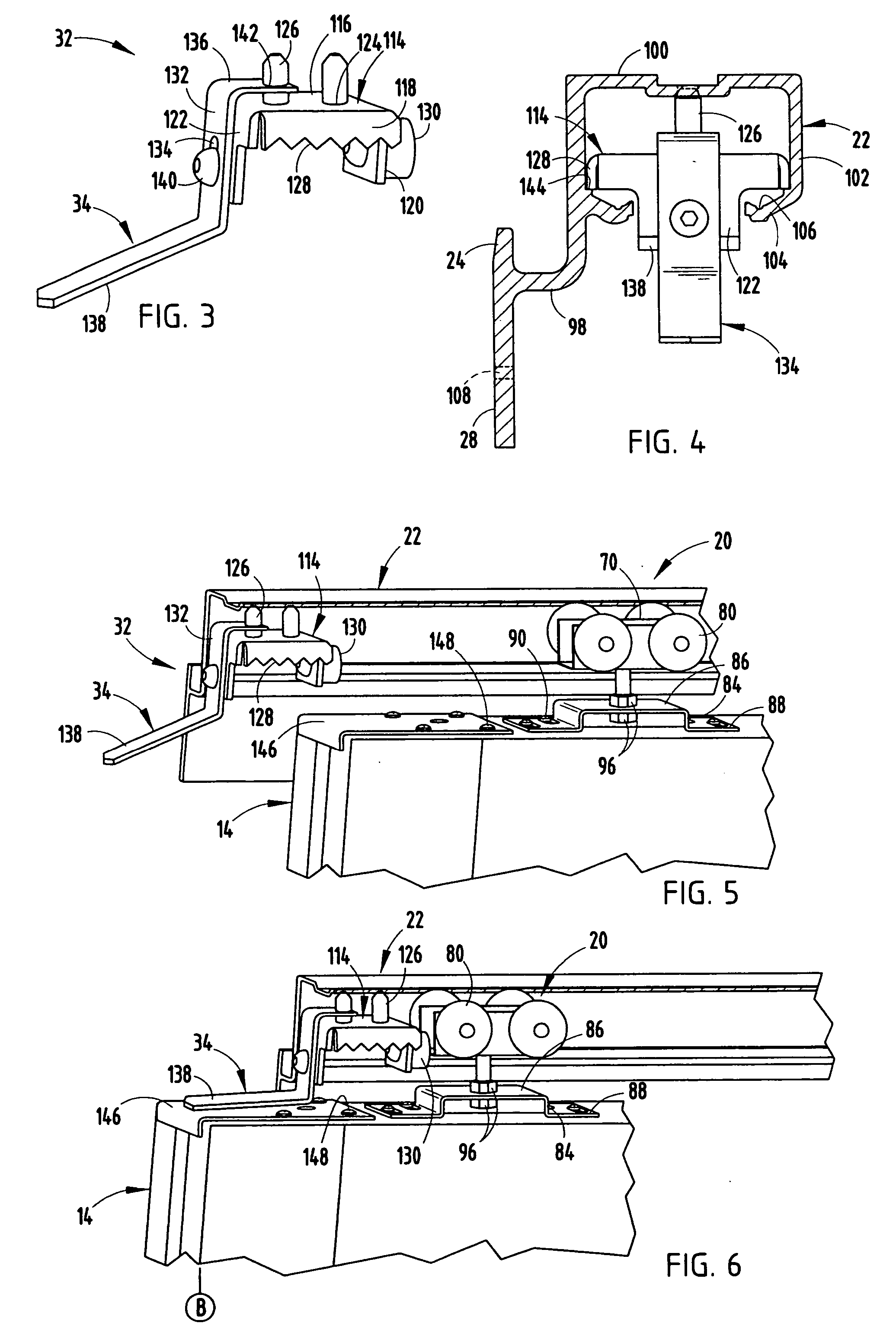
[0008] Still yet another aspect of the present invention is to provide a decelerator assembly adapted to slow the sliding movement of a door member slidably supported from a track member supported by a stationary panel member as the door member approaches a select one of a fully-open position and a fully-closed position, the decelerator assembly comprising a body portion adapted to be secured directly to the track member, and a spring member operably coupled with the body portion and adapted to frictionally engage an exposed surface of the door member when the door member is proximate a select one of a fully-open position and a fully-closed position, thereby decreasing a velocity of the door member prior to the door member reaching the select one of the fully-open position and the fully-closed position.
[0009] The present inventive partition panel assembly reduces the number of parts typical of support track assemblies associated with partition panel assemblies, and further reduces the skill required for installation thereof. Moreover, the present inventive partition panel assembly reduces the velocity of an included sliding door, thereby reducing noise associated with operation of the door and increasing the operating life of components of the partition panel assembly.

Problems solved by technology

Heretofore, the track assemblies commonly used are typically complicated in design involving a significant number of components and parts.
These complicated designs may require skilled personnel to install.
Further, these designs that include numerous parts are expensive to manufacture, package and ship to the appropriate destination for installation.
These configurations allow the transmission of significant impact forces from the door to the structural component when the door reaches the fully open or closed position, thereby resulting in structural degradation of the overall assembly, adding to the noise levels in the associated work area, etc.

Method used


Image

  • Partition panel assembly
  • Partition panel assembly
  • Partition panel assembly

Examples


Embodiment Construction

[0016] For purposes of description herein, the terms “upper,”“lower,”“right,”“left,”“rear,”“front,”“vertical,”“horizontal,” and derivatives thereof shall relate to the invention as oriented in FIG. 1. However, it is to be understood that the invention may assume various alternative orientations and step sequences, except where expressly specified to the contrary. It is also to be understood that the specific devices and processes illustrated in the attached drawings, and described in the following specification are exemplary embodiments of the inventive concepts defined in the appended claims. Hence, specific dimensions and other physical characteristics relating to the embodiments disclosed herein are not to be considered as limiting, unless the claims expressly state otherwise.

[0017] The reference numeral 10 (FIG. 1) generally designates the partition panel assembly embodying the present invention. In the illustrated example, the partition panel assembly 10 includes a stationary ...


PUM


Abstract

A partition panel assembly includes a stationary panel member having an exposed surface including a longitudinally-extending, downwardly-exposed channel, and a door member slidably supported from the stationary panel member for movement between a closed position and an open position. The partition panel assembly also includes a door member support assembly comprising a roller assembly operably coupled to the door member, and a support member having an upwardly-extending arm received within the channel of the stationary panel member, a downwardly-extending arm abutting the exposed surface of the stationary panel member, and a track member supporting the roller of the roller assembly such that the door member is slidably supported from the stationary panel member. The partition panel assembly further includes a decelerator assembly including a spring member secured to the track member and adapted to frictionally engage the door member when the door member is proximate the open or closed position, thereby decreasing a velocity of the door member prior to the door member reaching a fully opened or closed position.

Description

BACKGROUND OF THE INVENTION [0001] The present invention relates to a partition panel assembly that defines an ingress and egress opening therein and includes a door slidable between an open and closed position, and in particular a reduced-part door member support assembly and decelerator assembly. [0002] Typically, both the freestanding and the floor-to-ceiling partition panel assemblies define ingress and egress openings therein through which users migrate between private workstations and common work areas. In order to provide privacy in the workstations or to groups within common work areas, doors are typically provided in order to cover the openings or doorways defined within the partition panel assembly. These doors are commonly pivotally hinged at one side thereof, or slidably supported by a track assembly. [0003] Heretofore, the track assemblies commonly used are typically complicated in design involving a significant number of components and parts. These complicated designs ...

Claims


Application Information

Patent Timeline
Patent Type & Authority Applications(United States)
IPC IPC(8): E06B3/32E04H1/00
CPCE05D13/04E05D15/0652E05F5/003E05Y2201/11E05Y2201/684E06B3/4618E05Y2201/492E05Y2201/224E05Y2600/60E05Y2800/27E05Y2800/29E05Y2201/218E05Y2201/48E05Y2900/132E05Y2201/499
Inventor GRAVEL, DONALD P.ROBERTSON, OXANA
Owner STEELCASE INC
Learn More