Paper punch

a paper punch and paper punch technology, applied in the field of desk paper punches, can solve the problems of paper punches flying willy-nilly and end up on the floor, cumbersome emptying process of paper punch receptacles, and more problems

Inactive Publication Date: 2006-12-14
OFFICEMATE INT
View PDF14 Cites 20 Cited by
  • Summary
  • Abstract
  • Description
  • Claims
  • Application Information

AI Technical Summary

Benefits of technology

[0007] The present invention is a desk-top paper punch which is disclosed in several implementations. Each of the implementations incorporate the same novel features. The paper punch includes a drawer for removable insertion into the base of the paper punch, the drawer serving as a collection receptacle for paper punches (a / k / a chips) to be discarded. Once the drawer is near its chip capacity, the drawer is pulled out of the base for emptying. Means for viewing the contents of the drawer is provided. In one implementation, the view means is a transparent window which allows the viewer to know when the drawer in nearing its capacity for paper chips. In a second embodiment, the viewing means is at least one viewing aperture that perforate the top surface of the base of the paper punch that allows the user to view the drawer's contents. In either case, the user will know that it is time to empty the drawer which can easily be moved from the base for emptying and subsequently repositioned into the base.

Problems solved by technology

One disadvantage of prior art paper punches is that the process of emptying the paper punch receptacle is cumbersome.
This is more problematic in the case of larger, heavier duty desk-top paper punches.
In addition, when emptying prior art paper punches with deformable paper receptacle covers, discarded paper punches often fly willy-nilly and end up on the floor.
Furthermore, prior art paper punches do not allow the user to view the contents of the paper punch receptacle.
Even worse, the user may wait too long to empty the paper receptacle thereby causing the punch rod to come into contact with the paper punches, thereby causing dulling of the punch rods.

Method used


Image

  • Paper punch
  • Paper punch
  • Paper punch

Examples


Embodiment Construction

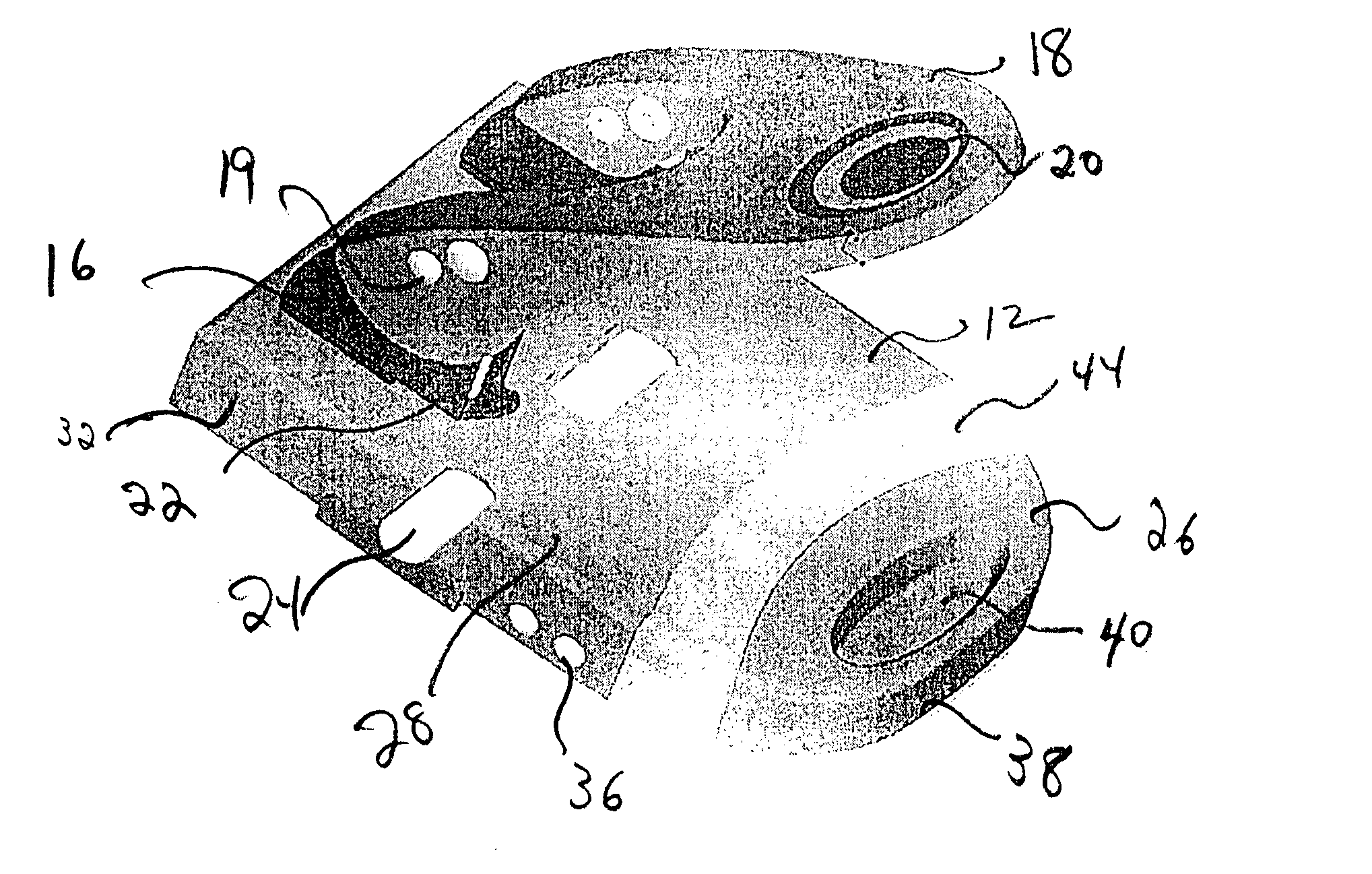
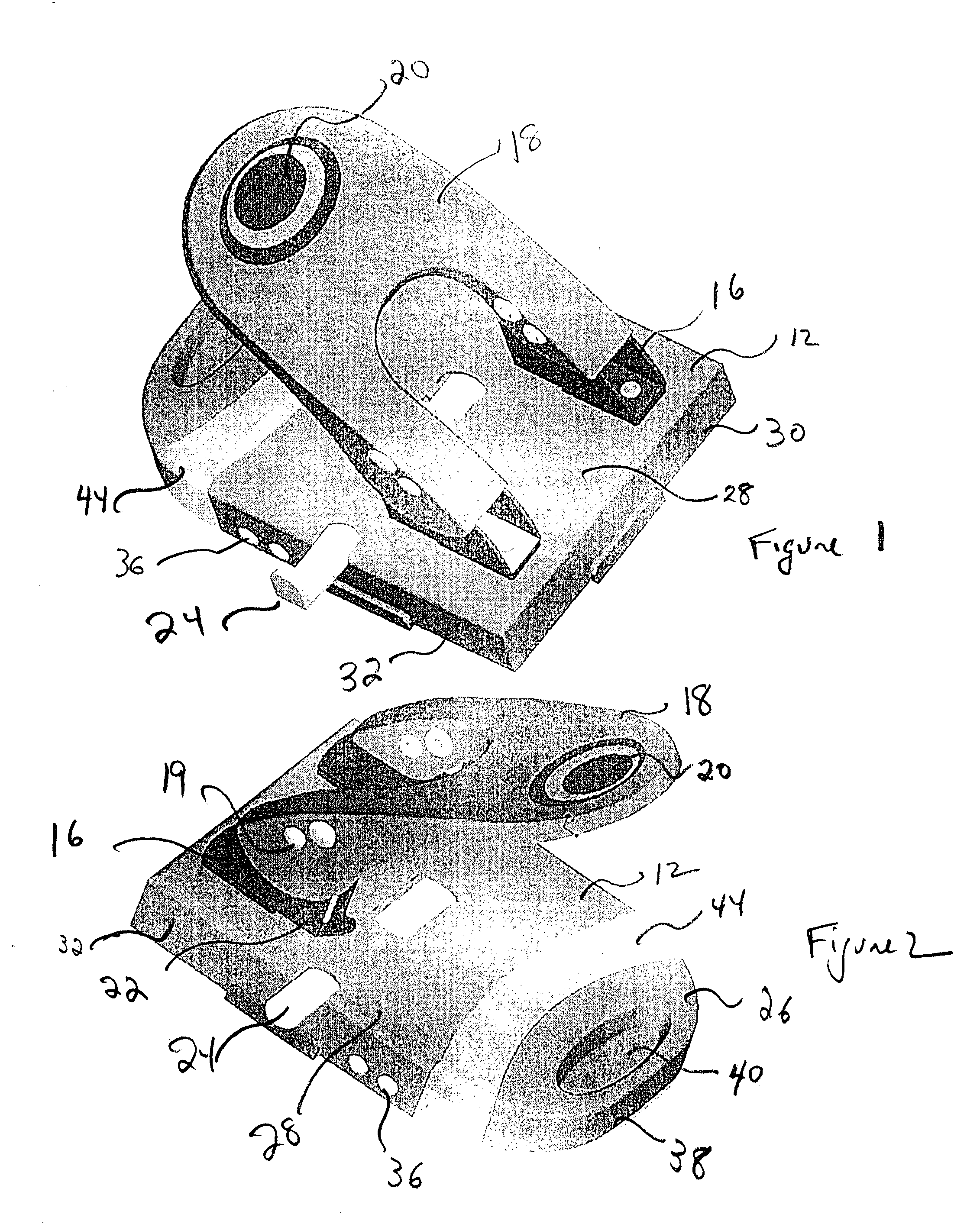
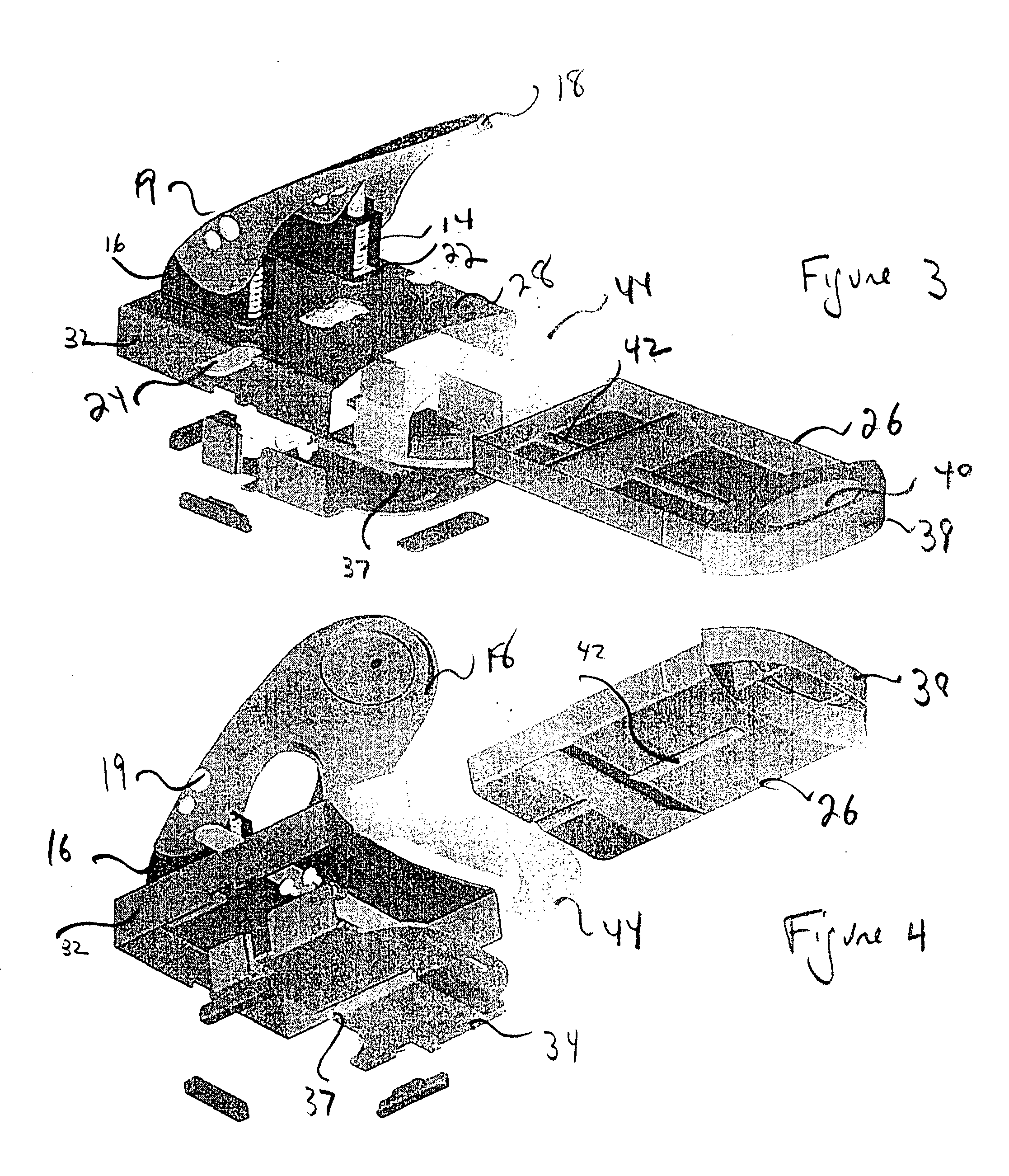
[0017] Referring to the drawings, the present invention is a desk-top paper punch. Four similar implementations of the present invention are contemplated—a two-hole punch version and a three-hole punch version, both presented in economy and deluxe versions. (The difference between the economy and deluxe versions is the size of the units and their respective components and therefore the paper stack capacity. In addition, the heavy-duty models include a padded handle for comfort of use.) The paper punch of the present invention includes prior art features such as a base 12, spring-loaded punch rods 14 which are enclosed in a punch-rod housing 16, and a handle 18 which is riveted to the punch rod housing using rivets 19. In the deluxe models, the handle includes a pad 20 to cushion the user's hand. Paper is positioned into the slot 22 defined by the punch rod housing 16 and the base 12. The positioning of the paper on the paper punch is guided through use of the paper guide 24. The pos...


PUM

PropertyMeasurementUnit
transparentaaaaaaaaaa
flexibleaaaaaaaaaa
timeaaaaaaaaaa

Abstract

A desk-top paper punch includes a drawer for removable insertion into the base of the paper punch, the drawer serving as a collection receptacle for paper punches to be discarded. Once the drawer is near its capacity, the drawer is pulled out of the base for emptying. Means for viewing the contents of the drawer is provided. In one implementation, the view means is a transparent window which allows the viewer to know when the drawer in nearing its capacity for paper chips. In a second embodiment, the viewing means is at least one viewing aperture that perforates the top surface of the base of the paper punch that allows the user to view the drawer's contents.

Description

FIELD OF THE INVENTION [0001] The present invention is a desk-top paper punch for punching holes in paper. More specifically, the present invention paper punch includes a collection drawer for collecting paper punches and means for viewing the contents of the collection drawer. BACKGROUND OF THE INVENTION [0002] Paper punches are well known in the prior art and are used to punch holes in paper so that the paper can be bound together. Paper punches are available in a variety of configurations ranging from hand-held one-hole punches, to desk-top two-hole punches for binding papers in a file folder to three-hole punches for binding papers in a loose-leaf type binder. All of these share common elements. [0003] Typical prior art desk-top paper punches include a base, punch rods, and a pivoting handle. The base has a top surface upon which a stack of papers is positioned. The one or more punch rods are utilized for punching holes in paper, said punch rods travel into punch apertures on th...

Claims


Application Information

Patent Timeline
Patent Type & Authority Applications(United States)
IPC IPC(8): B26D5/08
CPCB26F1/36B26D2007/0018Y10T83/8785
Inventor CHEN, PETERLEE, JUNGKUNLEE, KEVIN HUI-LIEN
Owner OFFICEMATE INT
Why Eureka
Try Eureka