
Garment hanger and molding apparatus

Inactive Publication Date: 2006-12-14
BRAITRIM U K
View PDF9 Cites 1 Cited by
  • Summary
  • Abstract
  • Description
  • Claims
  • Application Information

AI Technical Summary

Benefits of technology

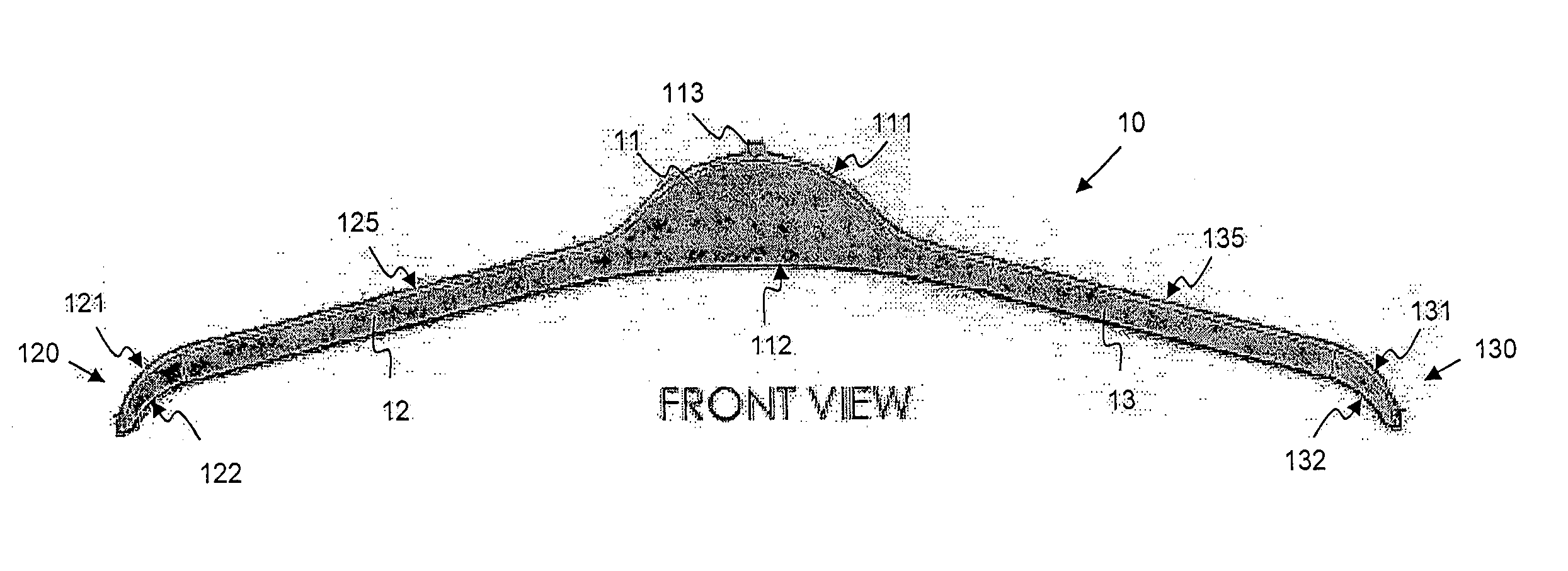
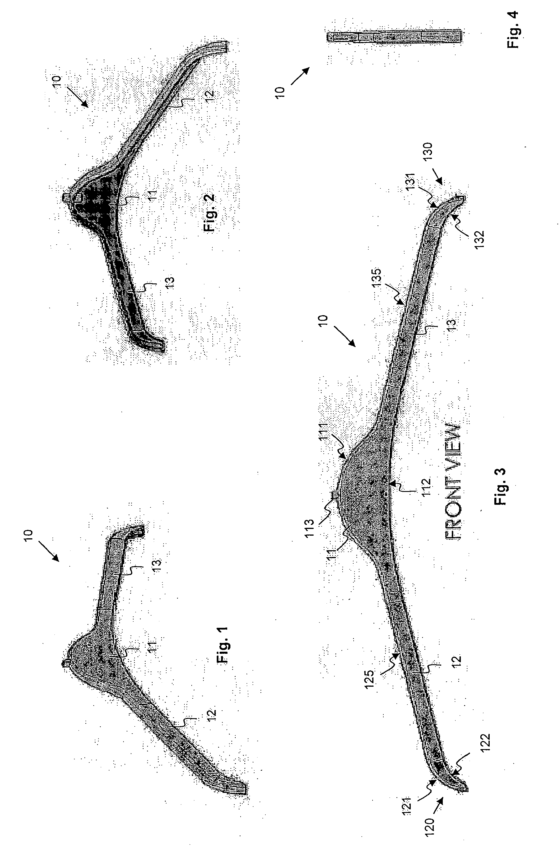
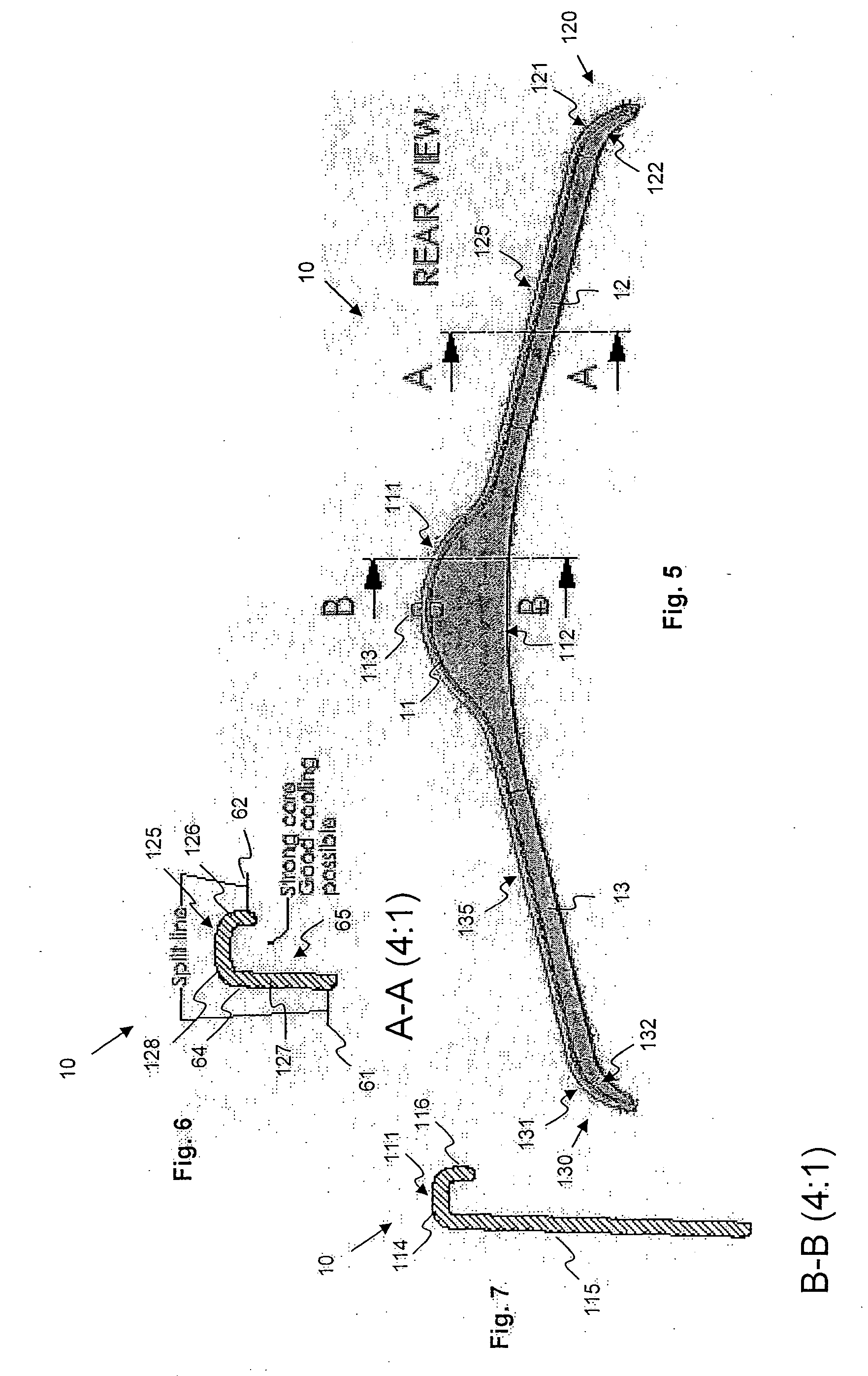
[0057] The J-section garment hanger of the invention has the additional advantage of a solid appearance, similar to that of a U-section garment hanger, in which no flanges are visible, while being more economical to produce than a solid garment hanger or a U-section garment hanger. It will be understood that in use a garment is in contact with the upper and front faces of the garment hanger

Problems solved by technology

Front and rear views of the garment hanger are therefore the same or similar, so that the upper and lower flanges are, in an undesirable manner for some applications, visible both from the front and rear of the garment hanger.
In order for the garment hanger to be removable from the mold the upper surface of the upper flange is therefore necessarily substantially planar and does not present a desirable rounded upper surface for receiving shoulders of a garment to be suspended from the garment hanger.
In order for the garment hanger to be removable from the mold the upper surface of the upper flange or portion is therefore necessarily substantially planar or of only limited curvature and does not present a desirable rounded upper surface for receiving shoulders of a garment to be suspended from the garment hanger.
Therefore, a narrowness with which a U-section garment hanger can be molded, that is a distance between the front and rear portions or legs, is limited by a limited narrowness of a core having sufficient strength not to bend or crack under pressures exerted during molding.
Moreover, due to their narrowness, the cores are too small and weak to locate cooling channels close to a surface of the core and therefore close to an opposed cavity, for rapid cooling of mold material.

Method used


Image

  • Garment hanger and molding apparatus
  • Garment hanger and molding apparatus
  • Garment hanger and molding apparatus

Examples


embodiment 10

[0044] Referring to FIGS. 10 to 14 a garment hanger 20 forming a further embodiment of the invention is similar to the first described embodiment 10. As best seen in FIGS. 12 and 14, the garment hanger 20 has an arm 23 having a longitudinal axis and an upper face 235. Dependent from the upper face 235 of the arm 23, proximate an outer, free end thereof, there is provided an L-shaped hook 234. A base of the L-shaped hook 234 is substantially parallel to the longitudinal axis and extends inward of the garment hanger arm. An elongate portion of the upper face 235 of the arm 23 substantially above, in use, the base of the hook 234 is cut away to form an elongate cutaway 236. The elongate cutaway 236 extends inward of the garment hanger arm 23 further than the base of the L-shaped hook to define a gap 237 between an inner extremity of the base of the L-shaped hook 234 and an inner extremity of the elongate cutaway 236. Thus, in use, the inner extremity of the L-shaped hook is spaced both...

embodiment 20

[0047] Referring to FIGS. 15 to 19 a garment hanger 30 forming a still further embodiment of the invention is similar to the second described embodiment 20. As best seen in FIGS. 17 and 19, the garment hanger 30 has an arm 33 having a longitudinal axis and an upper face 335. Dependent from the upper face 335 of the arm 33, proximate an outer, free end thereof, there is provided an L-shaped hook 334 similar to the L-shaped hook 234 of the previously described embodiment. However, in the garment hanger 30 the arm 33 is provided, inward of, and spaced from, the inward extending L-shaped hook 334, with a second, outward extending, L-shaped hook 3341 being a mirror image of the L-shaped hook 334. An elongate portion of the upper face 335 of the arm 33 substantially above, in use, the bases of the hooks 334 and 3341 is cut away to form an elongate cutaway 336. The elongate cutaway 336 extends further than a combined length of the bases of the L-shaped hooks 334 and 3341 to define a gap 33...


PUM

PropertyMeasurementUnit
Thicknessaaaaaaaaaa
Distanceaaaaaaaaaa

Abstract

An injection molding apparatus 80 has a cavity 64 and core 65 co-operatively defining a void of inverted J-shape transverse cross-section for molding a garment hanger 10. A first leg 115, 127 of the J-shape cross-section forms a front of the garment hanger, a base 111 of the J-shape cross-section forms a transversely arcuate upper face of the garment hanger for receiving shoulders of a garment to be suspended from the garment hanger and a second leg 116, 126, opposed to the first leg, and substantially shorter than the first leg, forms a return rear portion of the garment hanger. A garment hanger molded in the injection molding apparatus is also disclosed.

Description

Cross-Reference to Related Applications [0001] This application is a continuation in part of International Patent Application PCT / GB2004 / 004604 filed Nov. 2, 2004, claiming priority from GB 0325719.3 filed Nov. 4, 2003.FIELD OF THE INVENTION [0002] This invention relates to an injection molded garment hanger and a molding apparatus for molding such a garment hanger. BACKGROUND OF THE INVENTION [0003] Injection molded garment hangers of various transverse cross-sections are known. [0004] A known I-section garment hanger has a I-shaped transverse cross-section with upper and lower substantially planar flanges transverse to an interconnecting web. Front and rear views of the garment hanger are therefore the same or similar, so that the upper and lower flanges are, in an undesirable manner for some applications, visible both from the front and rear of the garment hanger. The garment hanger is molded with a mold split line along upper and lower faces of the upper and lower flanges respec...

Claims


Application Information

Patent Timeline
IPC IPC(8): A41D27/22A47G25/28B29C33/00B29C33/44
CPCA47G25/28B29C33/005B29L2031/735B29C2045/0034B29C33/44
Inventor HUNT, WILLIAM JOSEPH
Owner BRAITRIM U K
Learn More