Closing device

a closing device and drawer technology, applied in drawers, furniture parts, domestic applications, etc., can solve the problems of affecting the integrity of the elongated hollow housing, affecting the operation of the drawer and the closing device, and the inability to prevent the effect of minimal guiding, so as to avoid the distortion of the position of the guiding pin, the effect of strong and rigidity

Inactive Publication Date: 2006-12-14
HARN MARKETING
View PDF15 Cites 18 Cited by
  • Summary
  • Abstract
  • Description
  • Claims
  • Application Information

AI Technical Summary

Benefits of technology

[0011] The housing of the closing device of this invention is stronger and more rigid as it does not have a side slot. Also, the entire body of the rotating member is guided in the first portion of the front portion of the housing. This addresses the problem of initial rotational movement of the rotating member within the front portion of the housing and avoids the distortion of position of the guiding pin within the angular slot. As such, these improvements provides for a closing device that operates smoothly and is more reliable.
[0012] Also, the absence of a side slot on the housing as well as a side projection on the rotating member eases the assembly and manufacture of the closing device. The absence of the projection on the rotating member as well as its external shape which relatively conforms to the internal shape of the first portion allows for the rotating member to be easily inserted by sliding through the front of the housing.

Problems solved by technology

With this prior closing device, the integrity of the elongate hollow housing is compromised due to the second L-shaped axial slot disposed at its side.
In use, this minimal guiding is not always effective at preventing initial rotational movement.
Any rotational movement of the cylindrical member whilst the projection is engaged in the straight section of the second axial slot will distort the position of the guiding pin within the angular slot and cause the drawer and closing device to jam.
It has also been observed in practice, that the direct coupling of the resilient means to the cylindrical member causes friction which results in more force needing to be applied for the rotational movement of the cylindrical member.
This problem together with the problems of the preceding paragraph would inevitably cause the operation of the prior closing device to be not as smooth and reliable as desired.
Additionally, the assembly of the prior closing device is also undesirably complicated due to the side projection of the cylindrical member.
The second L-shaped axial slot also complicates the manufacturing of the hollow housing.

Method used


Image

  • Closing device
  • Closing device
  • Closing device

Examples


Embodiment Construction

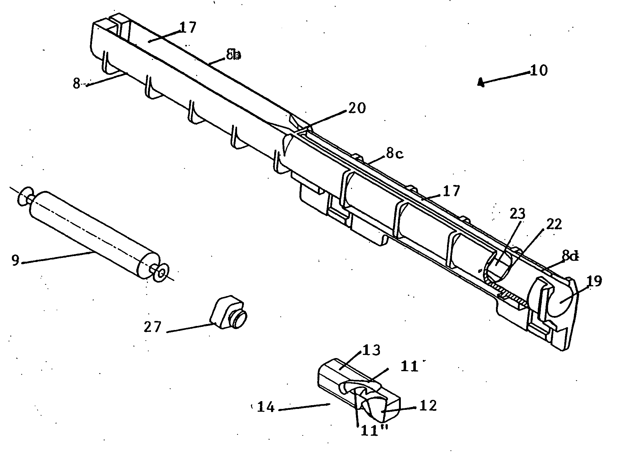
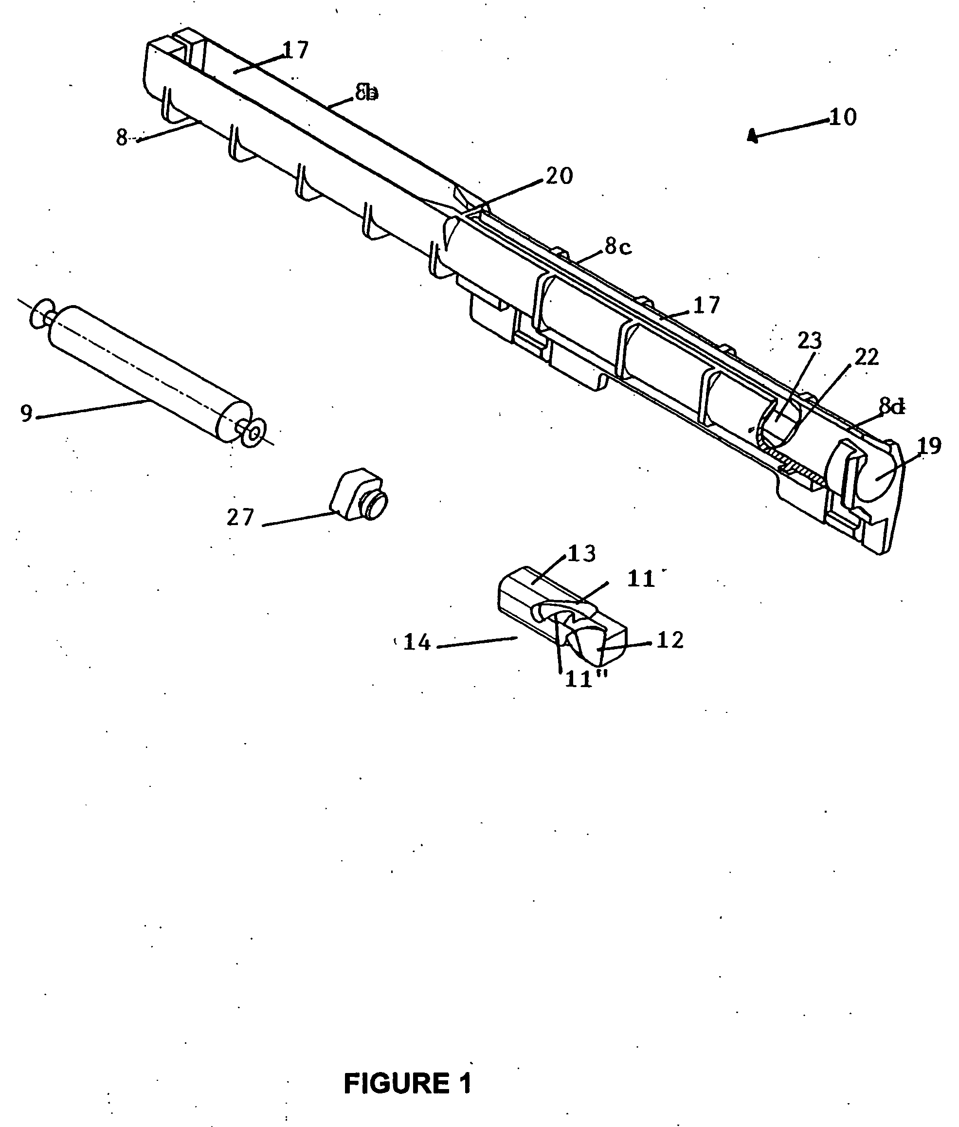
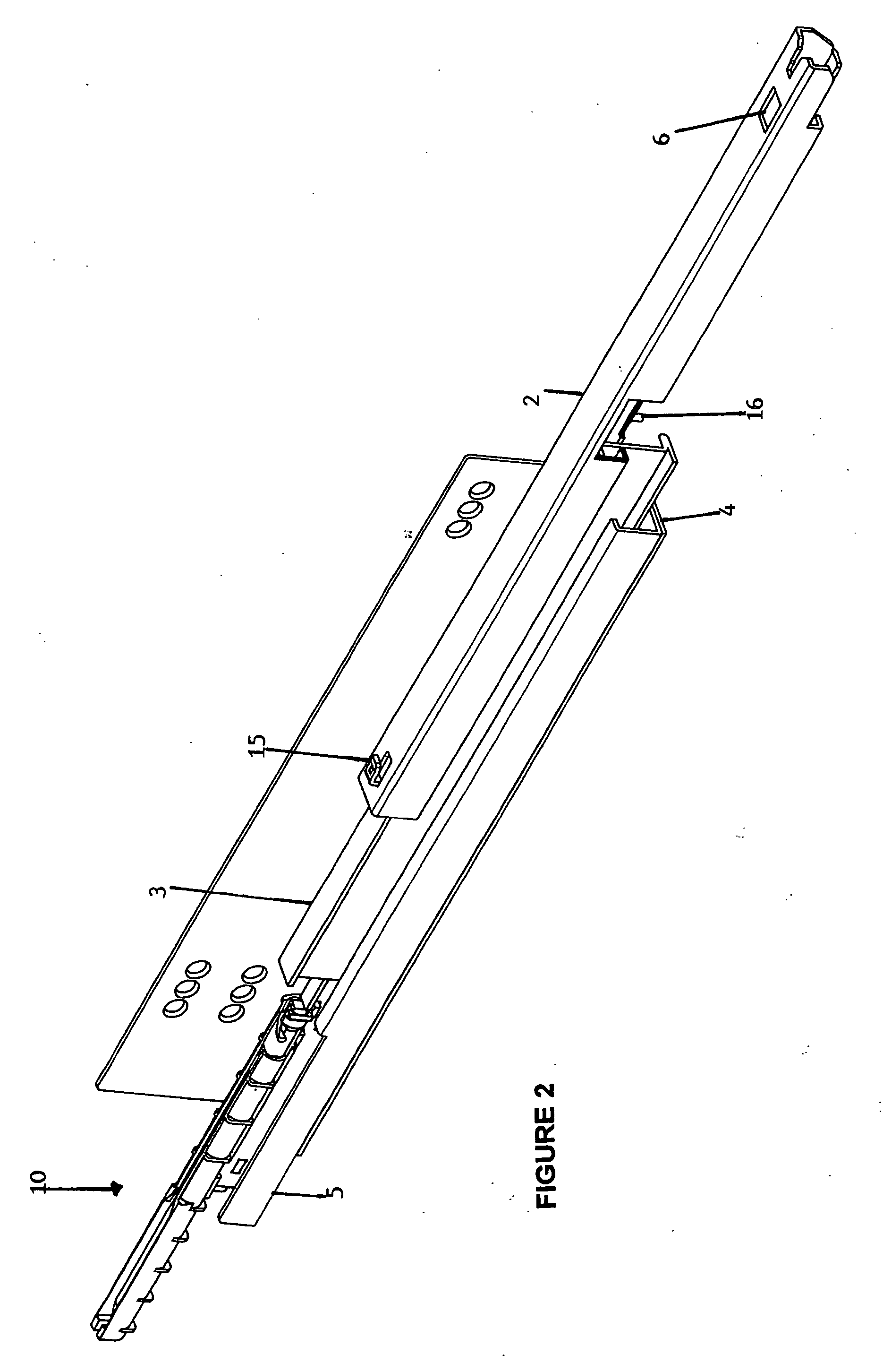
[0036] A closing device 10 for a drawer 7 of the present invention is shown in FIG. 1. The closing device 10 comprises an elongate hollow housing 8 which includes a front portion 8a and a rear portion 8b, wherein the housing has an axial slot 17 substantially along its length, a rotating member 14 slidably mounted in the front portion 8a of the housing and a resilient means 9 mounted in the rear portion 8b. The resilient means 9 attaches the rotating member 14 to the housing 8. As seen in FIG. 1, the resilient means in the form of a spring 9 is indirectly coupled to the rotating member 14 via an adaptor 27 which locks on the rotating member along with the resilient means. In a drawer assembly having a pull out guide system, the drawer 7 is attached with a top roller guide 2 having a back stopper 15 and a front clip 6 as shown in FIG. 2. The top roller guide 2 is further equipped with a guiding pin 16 downwardly extending from the bottom surface of the top roller guide 2. The back st...


PUM


Abstract

A closing device (10) for a drawer (7) comprising an elongate hollow housing (8) which includes a front portion (8a) and a rear portion (8b), a rotating member (14) slidably mounted in the front portion and a resilient means (9) mounted in the rear portion. The front portion (8a) of the housing (8) comprises first (8c) and second portions (8d) with the first portion having a rotation-preventing internal surface (23) and the second portion having a rotation-admitting internal surface (19). A locking step (22) is defined by the differing internal cross sections of the first and second portions. The rotation of the rotating member (14) in the first portion (8c) is prevented by the internal shape (23) of the first portion relative to the external shape (13) of the rotating member. The rotating member (14) has an angular slot (11) for receiving a guiding pin (16) which is downwardly extending from the bottom surface of a top roller guide (2). When the drawer (7) is pulled out, the action of the guiding pin (16) against a first face (11′) of the angular slot (11) moves the rotating member (14) axially through the first portion (8c) toward the second portion (8d). Upon reaching the locking step (22), the rotating member (14) is free to rotate within the second portion (8d) by action of the guiding pin (16) on the angular slot (11) and the rotation movement subsequently releases the guiding pin.

Description

[0001] This invention relates to a closing device for use in the furniture industry, and more particularly relates to a drawer closing device. [0002] For drawers without the closing device, the drawer that has been moved to a closed position will sometimes not be fully closed and the front panel of the drawer projects from the furniture body. As a result, it is possible for persons to bump against the front panel and injury of such persons may occur. Also, when the drawer has been pushed into the furniture body with too much energy, the drawer may again roll forward or rebound because of the excessive energy. DESCRIPTION OF THE PRIOR ART [0003] An existing drawer closing device has been disclosed in the Malaysian patent application no. PI 20021815. This existing closing device comprises an elongate hollow cylindrical housing having an axial slot extending from one end over at least a part of the body and a second L-shaped axial slot, a cylindrical member telescopically attached with...

Claims


Application Information

Patent Timeline
Patent Type & Authority Applications(United States)
IPC IPC(8): A47B88/00
CPCA47B88/047A47B88/467
Inventor LAM, HARN LIANLAM, HARN YAN
Owner HARN MARKETING
Why Eureka
Try Eureka