
Internet-of-Things remote factory prefabricated part production control system and method for energy station

A production control and remote technology, applied in the field of factory prefabricated parts production control system for remote energy stations of the Internet of Things, can solve the deformation of the position of the steel pipe and the flange, the bolt holes cannot be accurately located in the concentric position, and the positioning error is large, etc. problem, to achieve the effect of preventing position deformation

Active Publication Date: 2021-11-26
JIANGSU TUCHUANG SMART ENERGY CO LTD
View PDF10 Cites 2 Cited by
  • Summary
  • Abstract
  • Description
  • Claims
  • Application Information

AI Technical Summary

Problems solved by technology

[0003] In order to overcome manual welding, due to the large positioning error of the manual positioning flange, the bolt holes of the flanges at both ends of the steel pipe cannot be precisely in the concentric position. When the steel pipe and the flange are welded, due to the steel pipe and the French The flange plate is not fixed by external force. The high temperature generated during welding causes stress changes between the steel pipe and the flange plate, resulting in positional deformation of the steel pipe and the flange plate. The technical problem to be solved is: to provide a controllable method Prefabricated parts production control system and method for IoT remote energy station with precise positioning of blue plate and steel pipe

Method used


Image

  • Internet-of-Things remote factory prefabricated part production control system and method for energy station
  • Internet-of-Things remote factory prefabricated part production control system and method for energy station
  • Internet-of-Things remote factory prefabricated part production control system and method for energy station

Examples


Embodiment 1

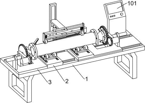
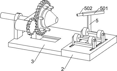
[0032] A factory prefabricated production control system for remote energy stations of the Internet of Things, including a support plate 1, an on-site control terminal 101, a remote control terminal 102, a data storage module 103, a network transmission 104, an adjustment module 105, a steel pipe rotation module 106, Flange push module 107, flange rotation module 108, welding module 109, steel pipe support mechanism, flange control mechanism, welding mechanism, steel pipe rotation mechanism and the second electric slide table 6, the upper right part of the support plate 1 is provided with an on-site control Terminal 101, field control terminal 101 is connected to remote control terminal 102 through network transmission 104, data storage module 103 is electrically connected to remote control terminal 102, adjustment module 105, steel pipe rotation module 106, flange push module 107, flange rotation module 108 and the welding module 109 are electrically connected to the field con...

Embodiment 2

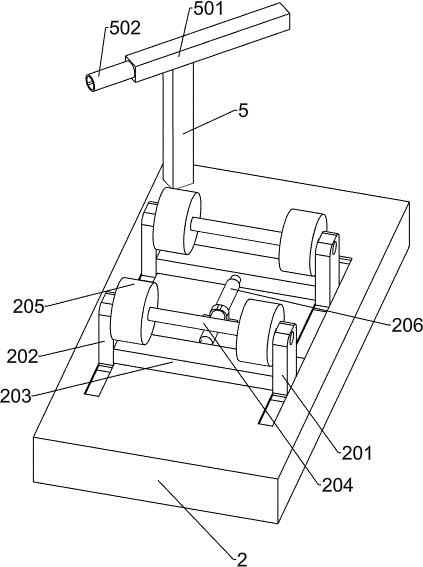
[0036] On the basis of Example 1, such as Figure 1-Figure 7 As shown, the steel pipe support mechanism includes a bottom plate 2, a steel pipe rotating frame and a two-way electric push rod 206, two slide grooves are arranged on the upper side of the bottom plate 2, two sets of steel pipe rotating frames are provided, and the two groups of steel pipe rotating frames are respectively slidably connected to the bottom plate Two chutes on the upper side of 2, the two-way electric push rod 206 is fixedly connected to the upper side of the bottom plate 2, the push rods at the front and rear ends of the two-way electric push rod 206 are respectively fixedly connected to two sets of steel pipe swivel frames, the two-way electric push rod 206 and the adjustment module 105 electrical connections, the steel pipe swivel frame includes a right vertical plate 201, a left vertical plate 202, a connecting plate 203, a rotating shaft 204 and a support wheel 205, and the right vertical plate 20...

Embodiment 3

[0044] On the basis of Example 2, such as Figure 1-Figure 7 As shown, when the flange is welded to the steel pipe, due to the local instantaneous high temperature of the steel pipe and the flange, the stress generated by the steel pipe and the flange cannot be released, resulting in the deformation of the positioning of the steel pipe and the flange, resulting in the deformation of the flange. When the flange and the steel pipe are deformed, after the positioning of the flange and the steel pipe is completed, the welding module 109 controls the welding mechanism to perform spot welding on the contact position between the flange and the steel pipe. After the spot welding is completed, the steel pipe rotation module 106 and the flange rotation module 108 control the steel pipe The rotation mechanism and the flange control mechanism rotate the flange and the steel pipe synchronously by 90 degrees, and the welding module 109 controls the welding mechanism to perform spot welding a...


PUM


Abstract

The invention relates to the field of factory prefabricated part production control systems, in particular to an Internet-of-Things remote factory prefabricated part production control system and method for an energy station. The system comprises a supporting plate, steel pipe supporting mechanisms, a flange control mechanism, welding mechanisms, a steel pipe rotating mechanism, a second electric sliding table and the like. One set of steel pipe supporting mechanisms and the flange control mechanism are arranged on the left portion of the upper side of the supporting plate, the second electric sliding table is arranged on the right portion of the upper side of the supporting plate, and the other set of steel pipe supporting mechanisms and the flange control mechanism are arranged on the upper side of the second electric sliding table. The welding mechanisms are arranged on the two sets of the steel pipe supporting mechanisms. The steel pipe rotating mechanism is arranged on the rear portion of the upper side of the supporting plate. After the steel pipe supporting mechanism and the flange control mechanism fix steel pipes and flange plates, automatic welding of the steel pipes and the flange plates is achieved, and bolt holes in the flange plates at the two ends of the steel pipes are made concentric and symmetrical.

Description

technical field [0001] The invention relates to the field of a factory prefabricated part production control system, in particular to a factory prefabricated part production control system for a remote energy station of the Internet of Things and a method thereof. Background technique [0002] Factory prefabricated parts are usually assembled from multiple parts. When the existing steel pipes and flanges are welded and prefabricated, the flanges are usually placed on both ends of the steel pipe manually, and the flanges at both ends of the steel pipe are placed The bolt holes of the two flanges are calibrated, the bolt holes of the two flanges are at the concentric position, and the welding is performed manually. Due to the large positioning error of the manual positioning of the flanges, the bolt holes of the flanges at both ends of the steel pipe cannot be accurate. The concentric symmetry of the steel pipe and the flange is welded, because the steel pipe and the flange ar...

Claims


Application Information

Patent Timeline
Patent Type & Authority Applications(China)
IPC IPC(8): B23K37/00B23K37/047B23K101/06
CPCB23K37/00B23K37/047B23K2101/06
Inventor 徐涛
Owner JIANGSU TUCHUANG SMART ENERGY CO LTD
Learn More