Method of designing equal conic intraocular lens

Active Publication Date: 2006-12-14
LENSTEC BARBADOS
View PDF2 Cites 19 Cited by
  • Summary
  • Abstract
  • Description
  • Claims
  • Application Information

AI Technical Summary

Problems solved by technology

The IOL can be made of various materials, and its optical surfaces can be very simple such as planes, spheres, or torics, or the surfaces can be quite complex and even designed for a specific eye.
In these non-ideal situatio

Method used


Image

  • Method of designing equal conic intraocular lens
  • Method of designing equal conic intraocular lens
  • Method of designing equal conic intraocular lens

Examples


Embodiment Construction

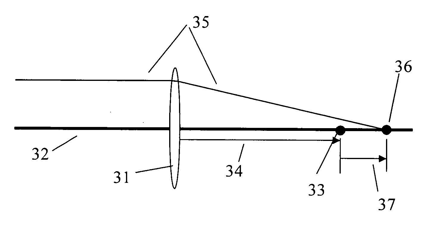
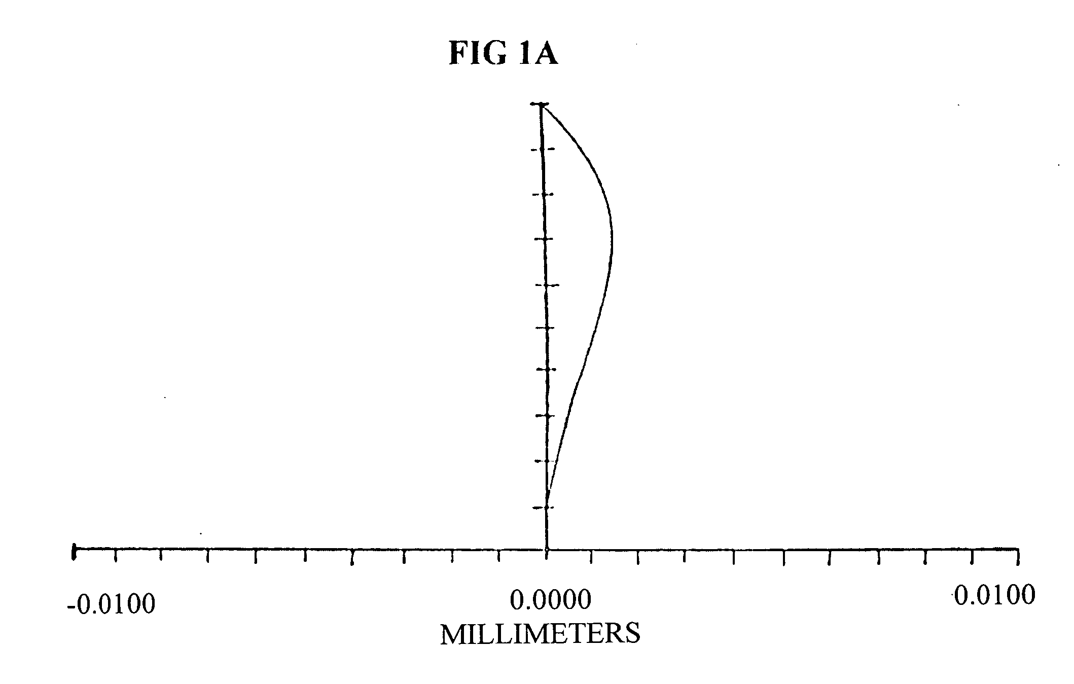
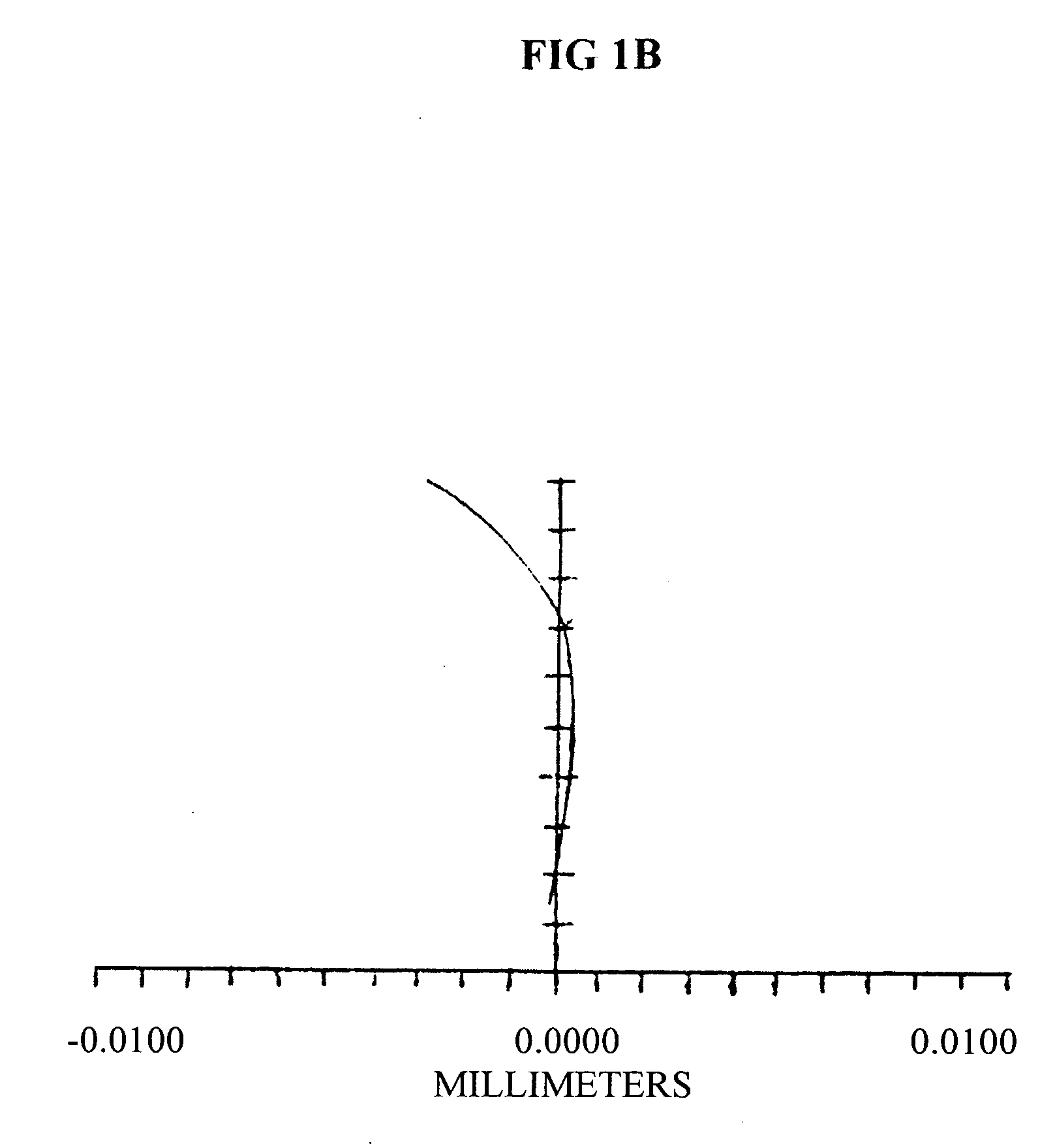
[0012] Given that the B-IOL must have symmetric surfaces (design requirement) and the paraxial power of the lens is the labeled power, the only true design parameter is the conic coefficient K. It is possible to set the conic constant so that the marginal ray (which just clears the edge of the clear aperture of the lens) for a distant object intersects the paraxial focus. The distance between the intersection of the off-axis ray with the optical axis and the paraxial focus is called the longitudinal aberration of the ray. For the case of zero longitudinal aberration at the marginal ray, the longitudinal aberration across the semi-diameter is graphed in FIG. 1.A. Note that in FIG. 1.A, the aberration at ray height of zero (the chief ray) is zero as is the ray at the edge of the lens. To reduce the overall sum of the longitudinal aberration, we can alternatively select the conic coefficient so that a ray at a height equal to 0.7071 of the clear aperture radius intersects the paraxial ...


PUM


Abstract

An intraocular lens, with equal conic surfaces, is intended to replace the crystalline lens in the posterior chamber of a patient's eye, in particular after a cataract extraction. The lens provides optical power to focus objects onto a patient's retina. In addition the lens surfaces are shaped to reduce optical aberrations at the retina and are tolerant to lens tilt and decentration within the eye. The lens is designed to have zero longitudinal ray aberrations at a specific ray height.

Description

This application claims the benefit of U.S. Provisional Application No. 60 / 690,664 filed Jun. 14, 2005.BACKGROUND OF THE INVENTION [0001] 1. Field of the Invention [0002] The present invention pertains to intraocular lenses within the posterior chamber, and more particularly, to aspheric, conic, or prolate intraocular lenses within the posterior chamber. [0003] 2. Description of Related Art [0004] It is often the case that an elderly patient will develop a condition called a cataract in the eye's crystalline lens. The cataract can develop to such a state that vision quality is significantly diminished to the point where surgical intervention is required to restore clear vision. In this surgical intervention, the crystalline lens containing the cataract is removed and an artificial lens is implanted. This artificial lens is called an intraocular lens (IOL). The IOL can be made of various materials, and its optical surfaces can be very simple such as planes, spheres, or torics, or the...

Claims


Application Information

Patent Timeline
IPC IPC(8): G02C7/02
CPCA61F2/16A61B3/0025A61F2/1613
Inventor CLOUGH, JOHNSARVER, EDWIN J.SANDERS, DONALD R.
Owner LENSTEC BARBADOS
Why Eureka
Try Eureka