Liquid crystal display device and method of fabricating the same

a technology of liquid crystal display and liquid crystal layer, which is applied in the direction of thin material processing, instruments, chemistry apparatus and processes, etc., can solve the problems of problematic light leakage, difficult to achieve a consistent arrangement of molecules in the liquid crystal layer, and difficulty in achieving light leakage in the region of the liquid crystal layer

Active Publication Date: 2006-12-14
LG DISPLAY CO LTD
View PDF8 Cites 37 Cited by
  • Summary
  • Abstract
  • Description
  • Claims
  • Application Information

AI Technical Summary

Benefits of technology

The invention aims to solve issues with both the rubbing alignment method and the photo-alignment method in LCD devices. The technical effect is to provide a more reliable and effective way of aligning the components of an LCD device during fabrication.

Problems solved by technology

The technical problem addressed in this patent text is to develop a method for aligning liquid crystals in LCD devices that does not require physical contact between the substrate and does not cause afterimages. The current rubbing alignment method and photo-alignment method have limitations in controlling the alignment of liquid crystals and may cause light leakage or afterimages. A new method is needed to overcome or minimize these issues.

Method used


Image

  • Liquid crystal display device and method of fabricating the same
  • Liquid crystal display device and method of fabricating the same
  • Liquid crystal display device and method of fabricating the same

Examples


Embodiment Construction

[0039] Reference will now be made in detail to the preferred embodiments of the invention, examples of which are illustrated in the accompanying drawings. Wherever possible, the same reference numbers will be used throughout the drawings to refer to the same or like parts.

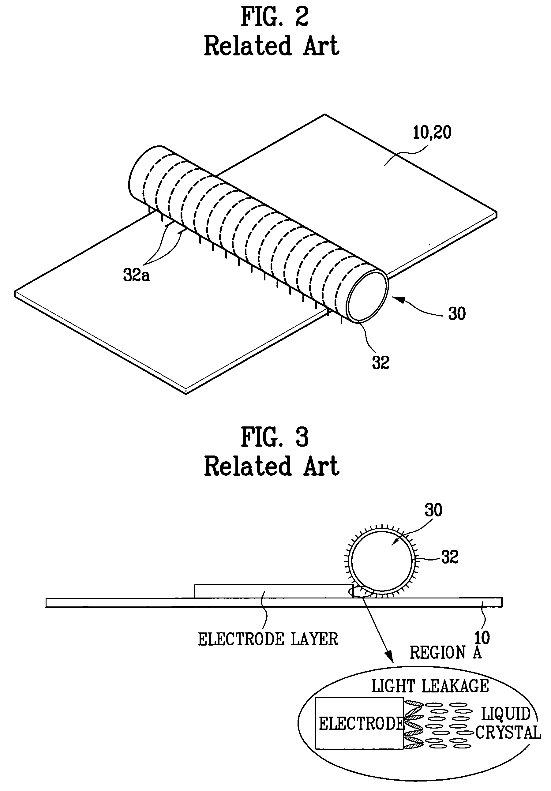
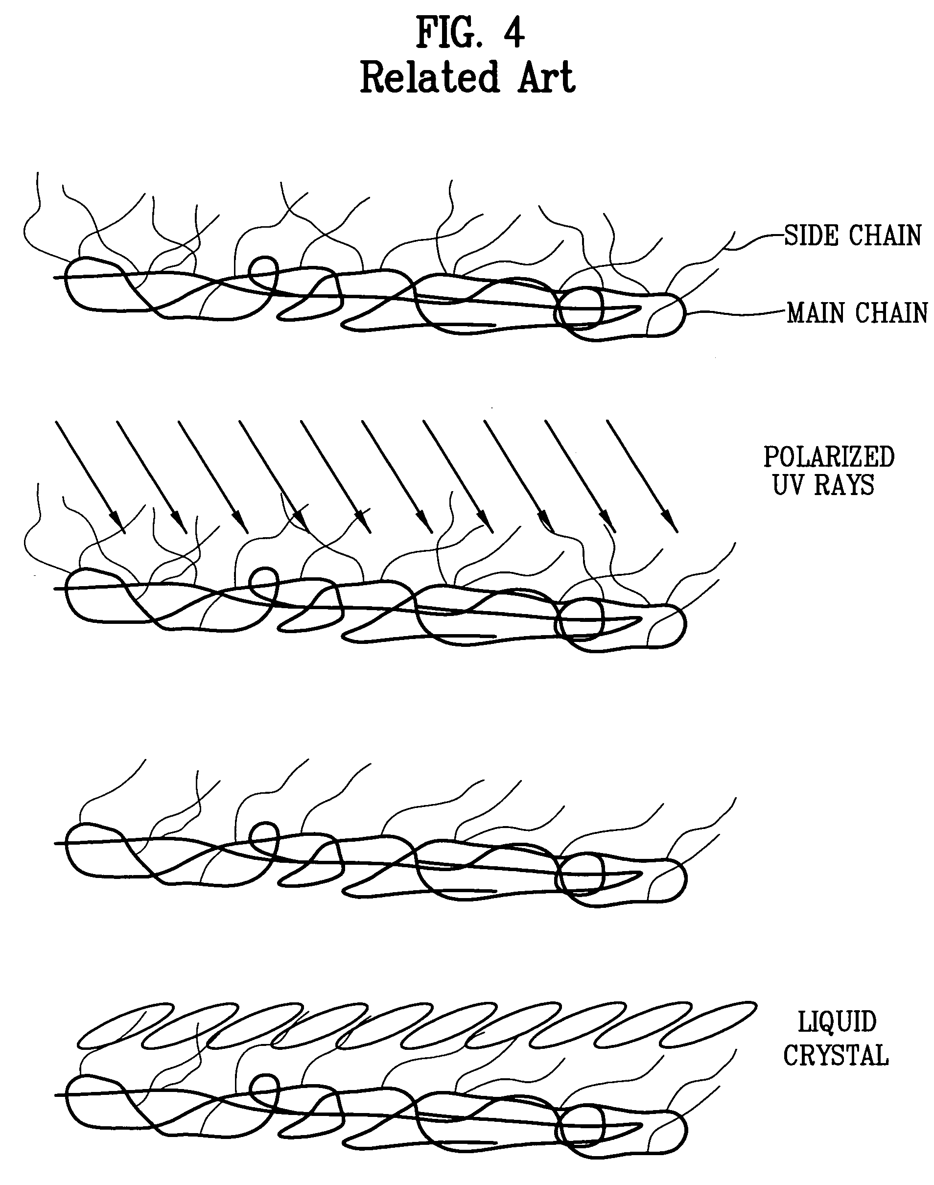
[0040] The invention addresses the problems of the conventional methods by combining a rubbing alignment method and a photo-alignment method. In other words, with the rubbing alignment method, when arrangement of a rubbing cloth becomes disordered or the rubbing cloth fails to contact the substrate, the alignment material coated on a region does not align with a constant alignment direction. Thus, the inventors of the present application recognized this problem and conceived a method for causing the portion(s) of the alignment material not aligned by the rubbing alignment method of the related art to be aligned by a photo-alignment method configured to address this need. Also, using the rubbing alignment method so...


PUM


Abstract

An LCD device includes first and second substrates, an alignment layer formed over at least one of the substrates, and a liquid crystal layer formed between the substrates. The alignment layer is formed of a mixture of rubbing alignment and UV alignment materials. A method of fabricating the LCD device includes preparing first and second substrates; coating an alignment layer over at least one of the substrates; performing a rubbing process on the substrate coated with the alignment layer; and irradiating polarized UV rays onto the substrate coated with the alignment layer, wherein the alignment layer is formed of a mixture of rubbing alignment a UV alignment materials. The rubbing process obtains high anchoring energy is obtained, thereby preventing afterimages. Also, the process of irradiating the polarized UV rays eliminates the problem of light leakage.

Description


Claims


Application Information

Patent Timeline
Owner LG DISPLAY CO LTD
Why Eureka
Try Eureka