Terminal structure and vacuum pump

a technology of terminal structure and vacuum pump, which is applied in the direction of mechanical equipment, machines/engines, coupling device connections, etc., can solve the problems of space and achieve the effect of preventing damage and high sealing property

Inactive Publication Date: 2006-12-14
EDWARDS JAPAN
View PDF7 Cites 24 Cited by
  • Summary
  • Abstract
  • Description
  • Claims
  • Application Information

AI Technical Summary

Benefits of technology

[0045] The present invention has been made in view of the above problems in the prior art. It is an object of the present invention to provide a terminal str

Problems solved by technology

However, they are flexible to a certain degree, so they are not easily damaged or the like by an exces

Method used


Image

  • Terminal structure and vacuum pump
  • Terminal structure and vacuum pump
  • Terminal structure and vacuum pump

Examples


Embodiment Construction

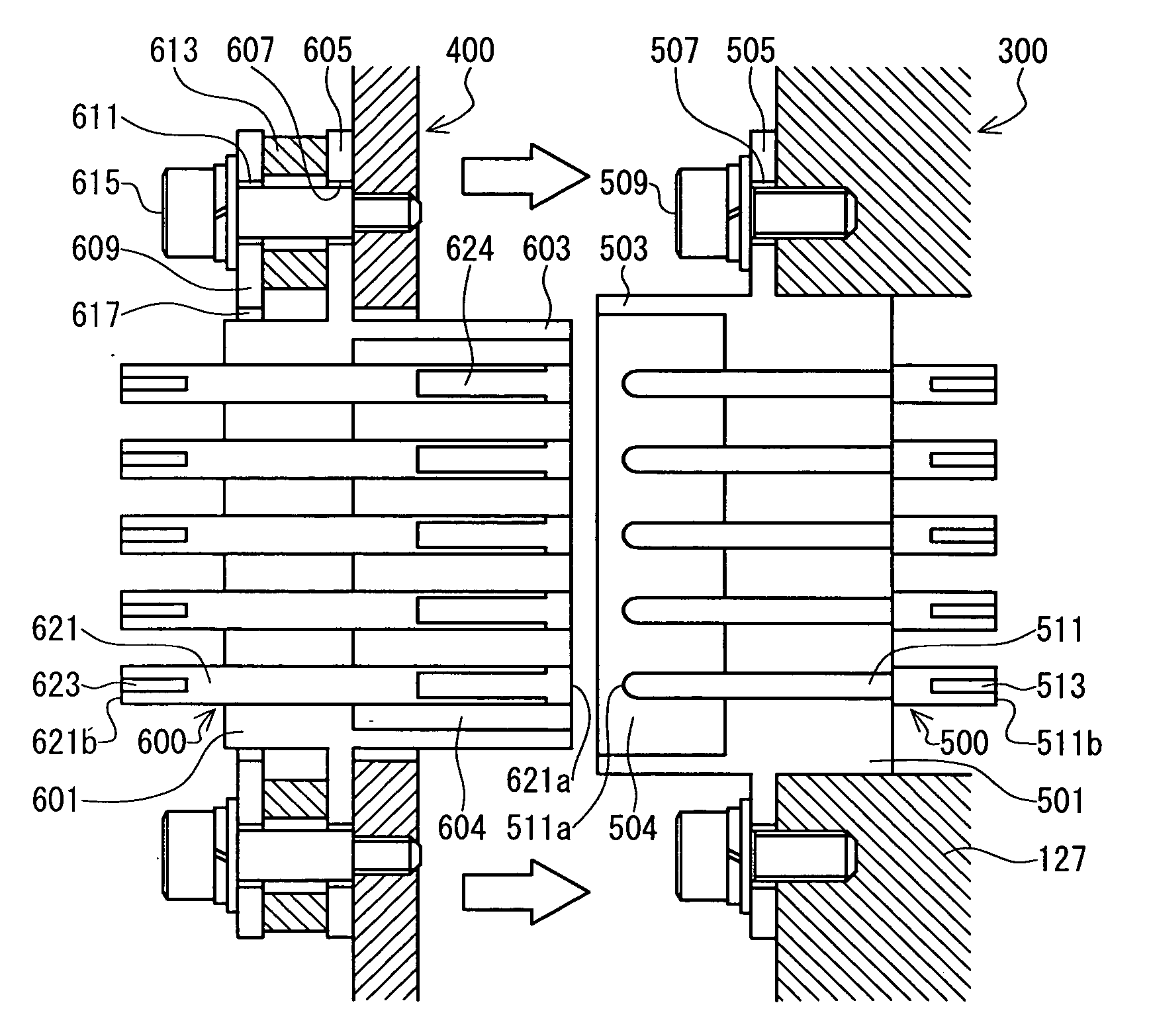
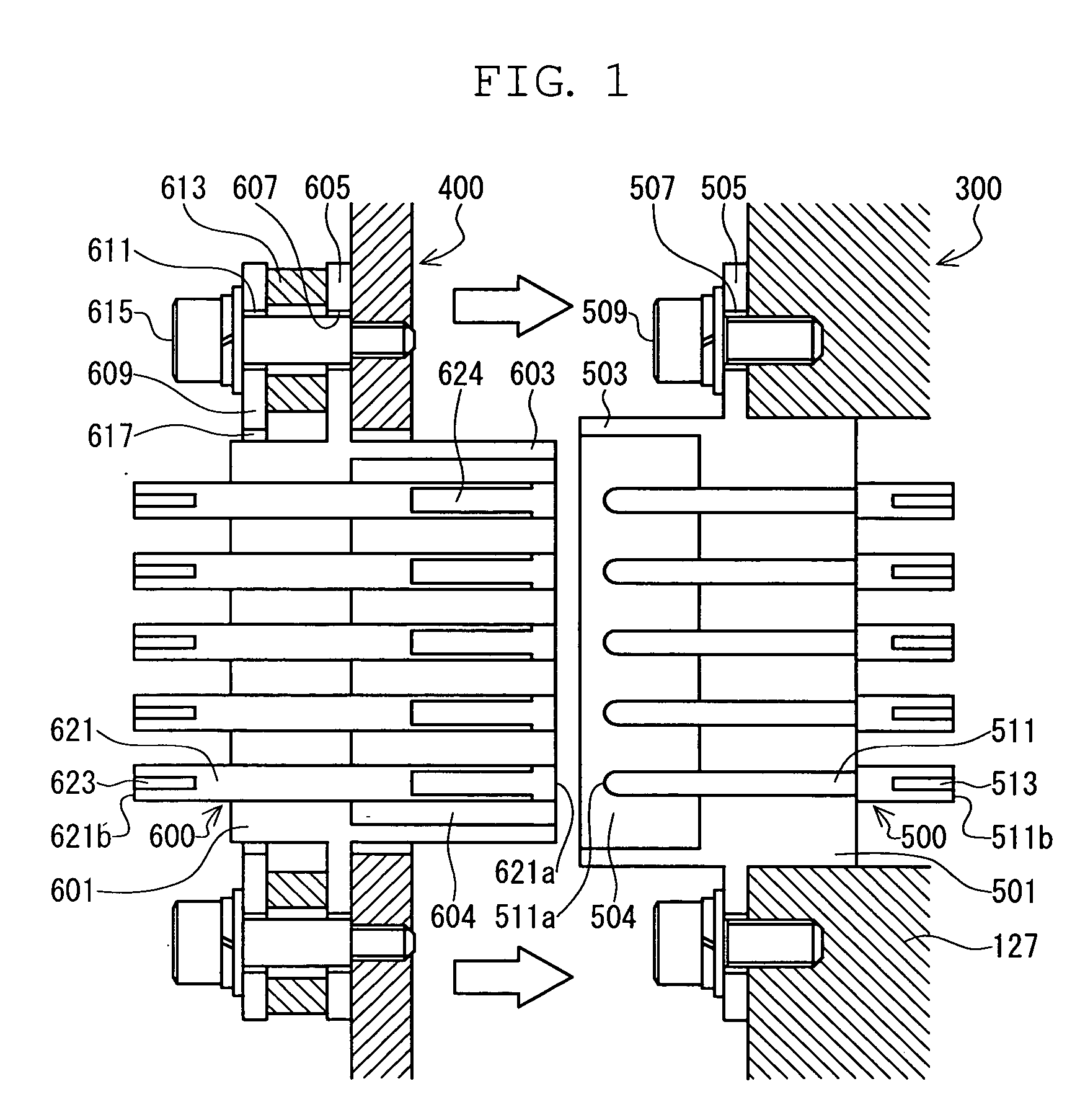
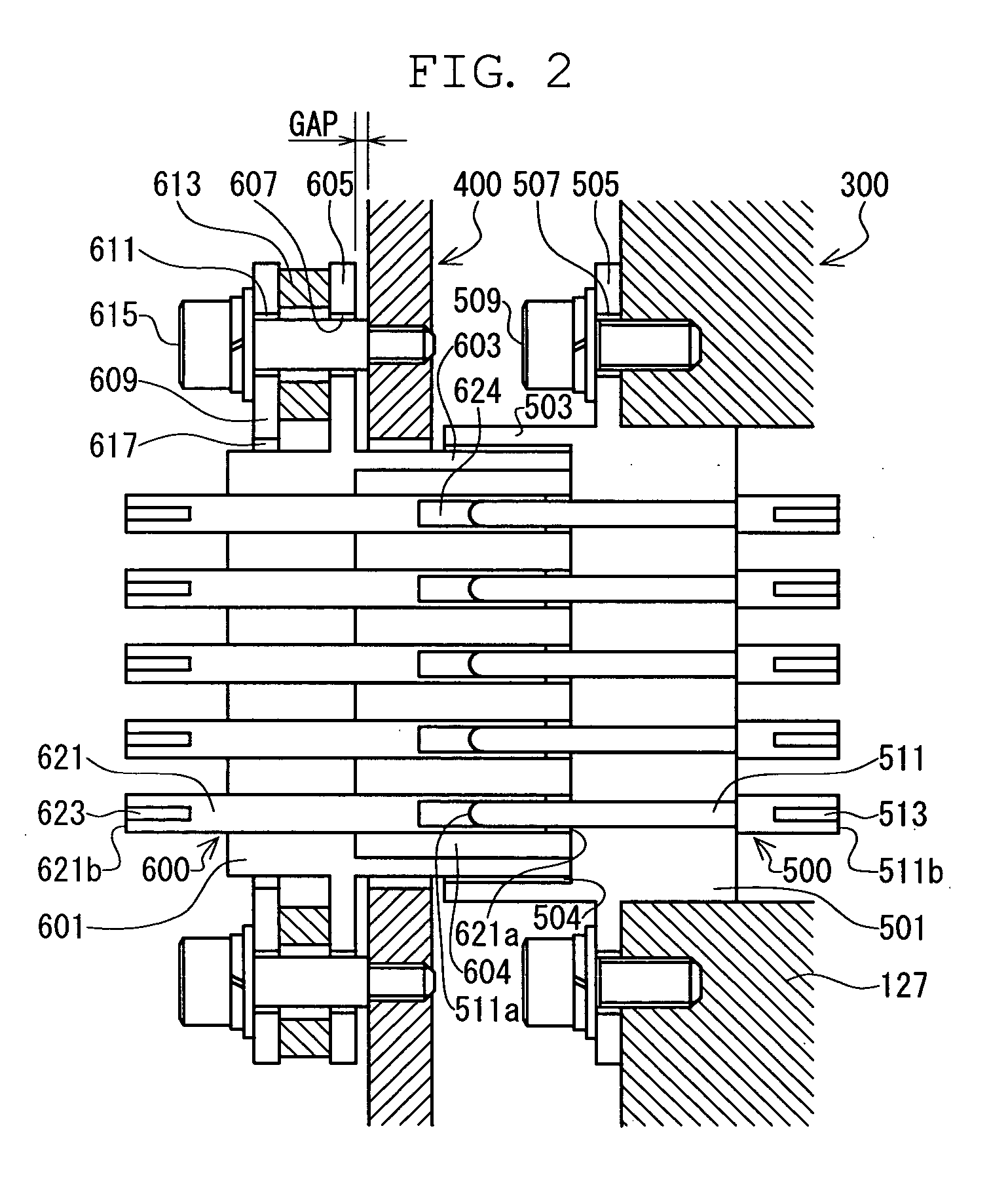
[0069] In the following, embodiments of the present invention will be described. FIG. 1 is a schematic view of a terminal structure according to a first embodiment of the present invention. In FIG. 1, a male connector 500 and a female connector 600 are arranged on a turbo molecular pump main body 300 side and a control device 400 side, respectively.

[0070] The male connector 500 has a cylindrical wall 503 protruding in a cylindrical fashion toward the control device 400 side from an outer peripheral edge of a thick bottom portion 501, and, inside the male connector 500, there is formed a columnar cavity 504 surrounded by the cylindrical wall 503 and the bottom portion 501. Further, a disc-like flange portion 505 is arranged around the bottom portion 501. In the flange portion 505, there are formed a plurality of through-holes 507, through which bolts 509 are passed to be inserted into and fixed to an outer cylinder 127 of the turbo molecular pump main body 300.

[0071] Forty-one male...


PUM


Abstract

Provided are a terminal structure capable of preventing damage due to an excessive force and having high sealing property, and a vacuum pump to which the terminal structure is applied. When a control device (400) undergoes transition to a turbo molecular pump main body (300), a cylindrical wall (603) of a female connector (600) is fit-engaged with a cavity (504) of a male connector (500). As the connection progresses, head portions (511a) at one ends of male pins (511) are inserted into pin insertion elongated holes (624). When, after that, a forward end of the cylindrical wall (603) of the control device (400) abuts a bottom portion (501) of the female connector (600), the female connector (600) on the control device (400) side, which is of low rigidity, is pushed back against an elastic force of waved washers (613). As a result, even when an excessive force is applied to the female connector (600) and the male connector (500), the force can be mitigated through deformation of the waved washers (613), so there is no fear of the connectors suffering damage.

Description

BACKGROUND OF THE INVENTION [0001] 1. Field of the Invention [0002] The present invention relates to a terminal structure and a vacuum pump, and in particular, to a terminal structure capable of preventing damage due to an excessive force and having high sealing property, and a vacuum pump to which the terminal structure is applied. [0003] 2. Description of the Related Art [0004] As a result of recent developments in electronics, there is a rapidly increasing demand for semiconductor devices such as memories and integrated circuits. [0005] Such semiconductor devices are manufactured by doping semiconductor substrates of a very high purity with impurities to impart electrical properties thereto, by forming minute circuits on the semiconductor substrates through etching, etc. [0006] In order to avoid the influences of dust in the air, etc., such operations must be conducted in a chamber in a high vacuum state. To evacuate this chamber, a vacuum pump is generally used; in particular, a...

Claims


Application Information

Patent Timeline
IPC IPC(8): H01R13/64
CPCH01R13/631H01R13/6315Y10S439/901F04D19/04F04D25/0693H01R13/74
Inventor KABASAWA, TAKASHIOKUDERA, SATOSHISAKAGUCHI, YOSHIYUKI
Owner EDWARDS JAPAN
Why Eureka
Try Eureka