Venous valve, system, and method

a technology of venous valves and lumens, applied in the field of venous valves, systems and methods for use in the lumens, can solve the problems of chronic venous insufficiency, requiring invasive surgical procedures, swelling and ulcers of the leg,

Active Publication Date: 2006-12-14
BOSTON SCI SCIMED INC
View PDF99 Cites 157 Cited by
  • Summary
  • Abstract
  • Description
  • Claims
  • Application Information

AI Technical Summary

Problems solved by technology

When valves fail, blood can pool in the lower legs resulting in swelling and ulcers of the leg.
The absence of functioning venous valves can lead to chronic venous insufficiency.
Techniques for both repairing and replacing the valves exist, but are tedious and require invasive surgical procedures.
Prosthetic valves can be transplanted into the venous system, but current devices are not successful enough to see widespread usage.

Method used


Image

  • Venous valve, system, and method
  • Venous valve, system, and method
  • Venous valve, system, and method

Examples


Embodiment Construction

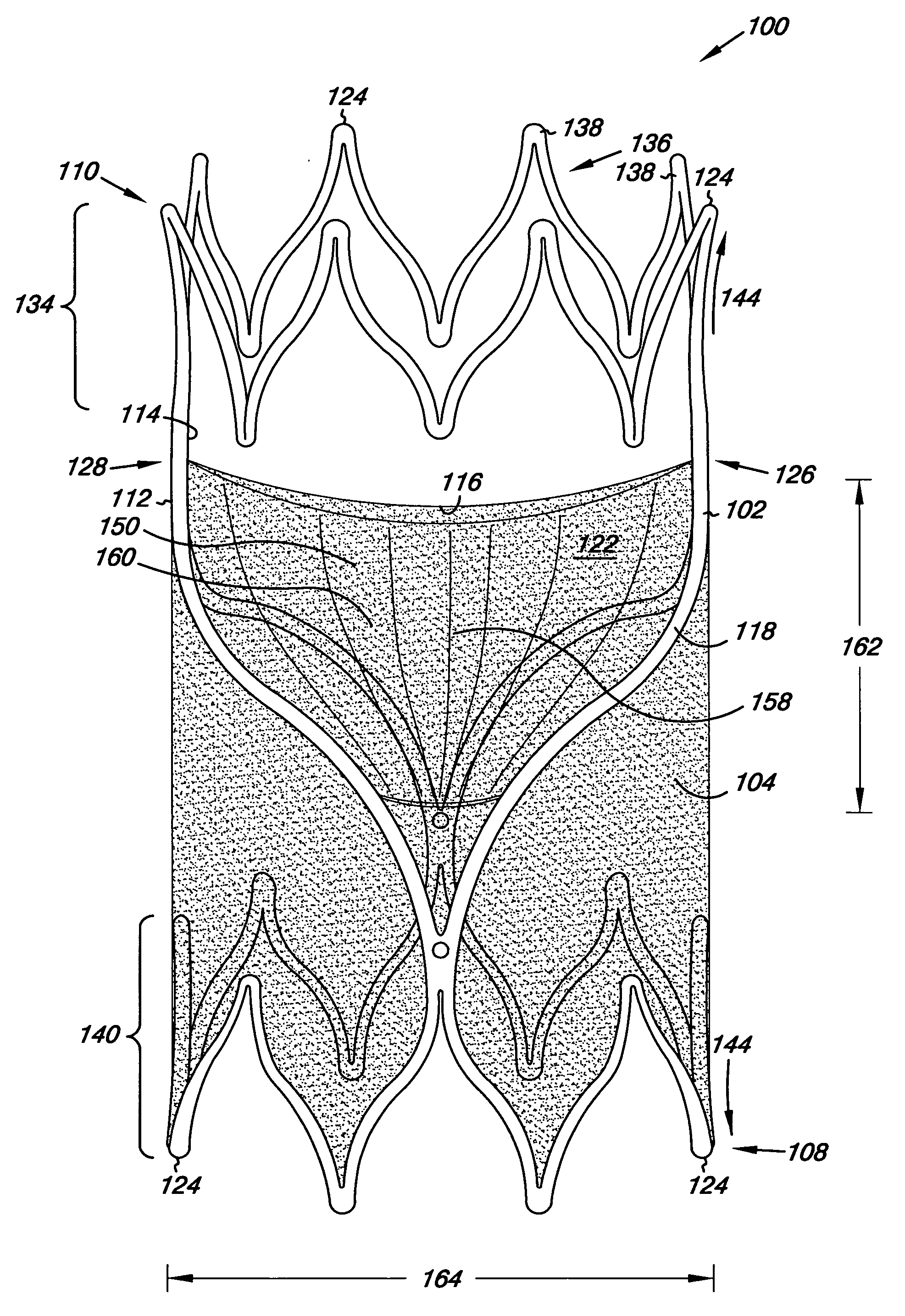
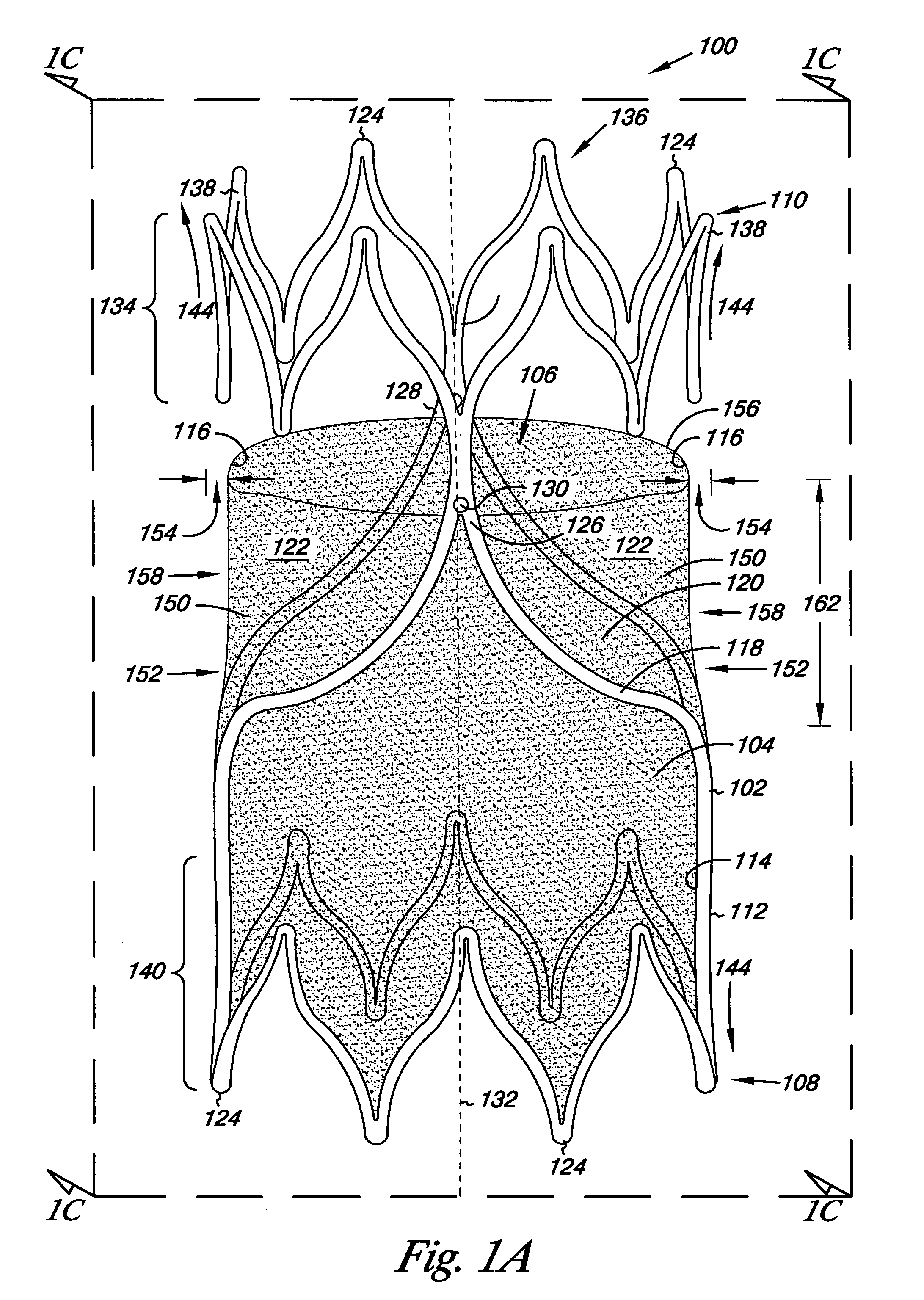
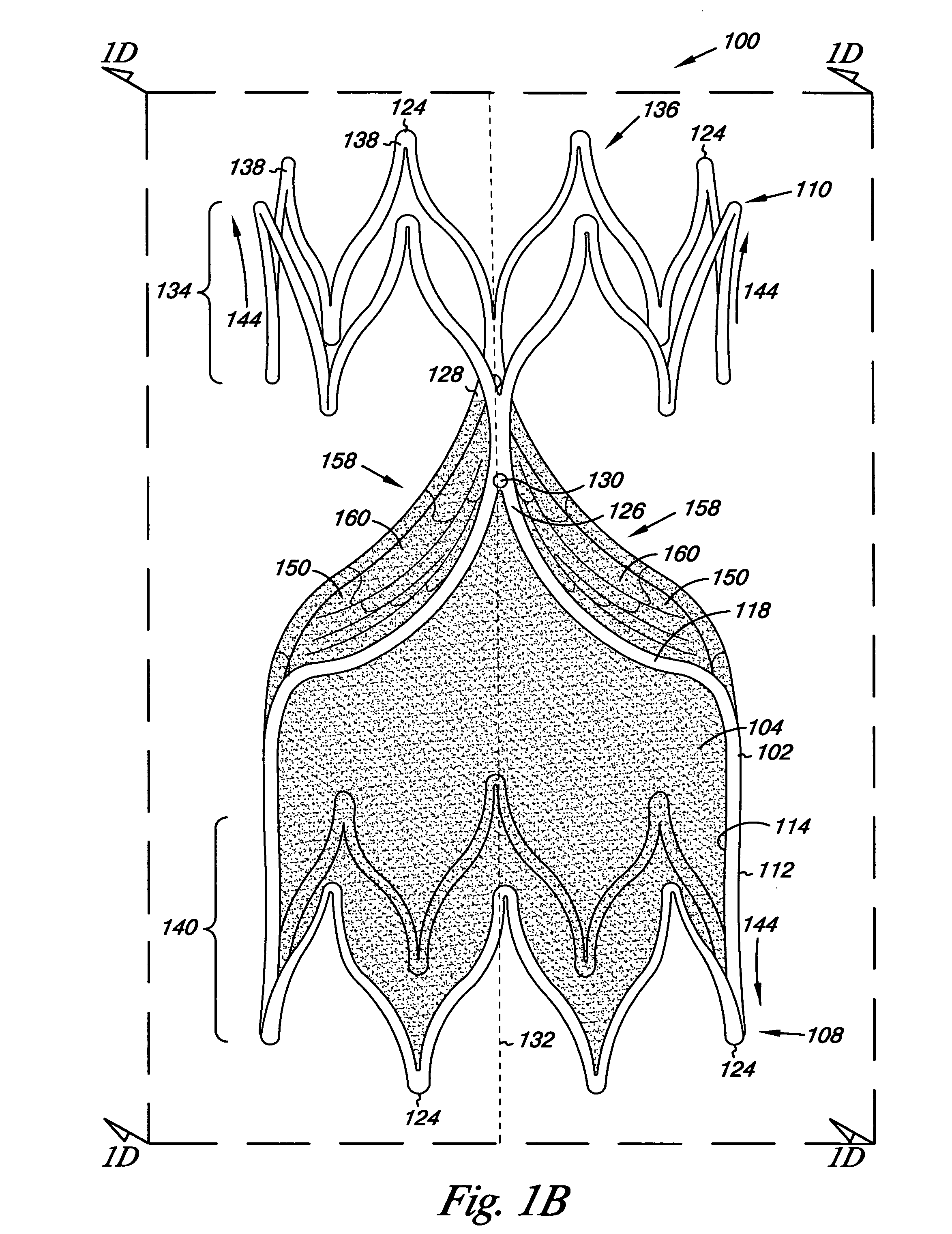
[0019] Embodiments of the present invention are directed to an apparatus, system, and method for valve replacement or augmentation. For example, the apparatus can include a valve that can be used to replace or augment an incompetent valve in a body lumen. Embodiments of the valve can include a frame and cover that can be implanted through minimally-invasive techniques into the body lumen. In one example, embodiments of the apparatus, system, and method for valve replacement or augmentation may help to maintain antegrade blood flow, while decreasing retrograde blood flow in a venous system of individuals having venous insufficiency, such as venous insufficiency in the legs.

[0020] The figures herein follow a numbering convention in which the first digit or digits correspond to the drawing figure number and the remaining digits identify an element or component in the drawing. Similar elements or components between different figures may be identified by the use of similar digits. For e...


PUM


Abstract

A venous valve with a frame and a cover on the frame for unidirectional flow of a liquid through the valve.

Description

FIELD OF THE INVENTION [0001] The present invention relates to apparatus, systems, and methods for use in a lumen; and more particularly to a valve apparatus, systems, and methods for use in the vasculature system. BACKGROUND OF THE INVENTION [0002] The venous system of the legs uses valves and muscles as part of the body's pumping mechanism to return blood to the heart. Venous valves create one way flow to prevent blood from flowing away from the heart. When valves fail, blood can pool in the lower legs resulting in swelling and ulcers of the leg. The absence of functioning venous valves can lead to chronic venous insufficiency. [0003] Techniques for both repairing and replacing the valves exist, but are tedious and require invasive surgical procedures. Direct and indirect valvuoplasty procedures are used to repair damaged valves. Transposition and transplantation are used to replace an incompetent valve. Transposition involves moving a vein with an incompetent valve to a site with...

Claims


Application Information

Patent Timeline
Patent Type & Authority Applications(United States)
IPC IPC(8): A61F2/06A61F2/84
CPCA61F2/2418A61F2/2475A61F2250/0098A61F2220/0016A61F2/2412A61F2220/0066A61F2220/0075A61F2230/0013A61F2220/005A61B90/39A61F2/2409
Inventor HILL, JASON P.SHOEMAKER, SUSAN M.KOKATE, JAYDEEP Y.
Owner BOSTON SCI SCIMED INC
Why Eureka
Try Eureka