Implantable vascular device

a vascular device and implantable technology, applied in the field of medical devices, can solve problems such as compounded problems, and achieve the effects of preventing tilting, improving conformity with the vessel, and preventing tilting

Inactive Publication Date: 2009-10-20
COOK MEDICAL TECH LLC
View PDF3 Cites 56 Cited by
  • Summary
  • Abstract
  • Description
  • Claims
  • Application Information

AI Technical Summary

Benefits of technology

[0008]In another aspect of the invention, the valve includes a frame that is covered by a piece of biocompatible material, preferably an Extracellular Collagen Matrix (ECM) such as small intestinal submucosa (SIS) or another type of submucosal-derived tissue. Other potential biomaterials include allographs such as harvested native valve tissue. The material is slit or otherwise provided with an opening along one axis to form two triangular valve leaflets over a four-sided frame. In the deployed configuration, the leaflets are forced open by normal blood flow and subsequently close together in the presence of backflow to help eliminate reflux. Other configurations include a two-leaflet valve having an oval or elliptically shaped frame, and valves having three or more legs and associated leaflets, which provide a better distribution of the load exerted by the column of fluid acting on the leaflets.
[0011]A second series of embodiments include centering support structure, such as a plurality of lateral elements or arms and / or supplemental legs, that extends laterally from the valve portion to provide additional contact points along the circumference of the vessel for longitudinal support, contact points being generally defined as the bends which typically supply concentrated radial force against the vessel wall (as opposed to the struts that although in contact the vessel wall, typically supply less radial force). Additionally, the lateral elements, which are preferably positioned behind the leaflets and interposed between the leaflet and vessel wall, can offer protection to the leaflets so that they are at least partially blocked and generally unable to adhere to the vessel wall, which can collapse onto the leaflets due to how the valve radially expands and conforms to the vessel. The lateral elements or arms can comprise separate components attached to the basic valve portion frame, or the frame itself can comprise multiple elements or subassemblies that can be assembled to form a closed valve portion frame with two laterally extending arms. Each lateral arm can include one contact point or additional contact points for added stability.
[0012]In another embodiment, the centering support structure comprises two lateral arms, which protect the two leaflets and provide longitudinal support, and two supplemental legs about the distal end of the valve portion for further stabilization to prevent tilting. One method of forming the frame includes attaching two zig-zag or serpentine-shaped stents end to end, with struts, sutures, or another well-known mechanism. Each zig-zag stent comprises a four or more serpentine sections with at least two opposite sections comprising either lateral arms (proximal stent) or supplemental legs (distal stent), with the other two serpentine sections on each stent comprising a half of one of the valve section legs. Strut lengths, wire diameters, eye diameters, and angles and widths of serpentine sections can be varied to produce optimum radial pressure that the device exerts on the vessel wall, depending on the size of the valve and vessel diameter. The optimal radial pressure is one at which the valve conforms to the vessel and prevents reflux without causing erosion or damage to the vessel wall that could lead to rupture.
[0013]In the double serpentine stent embodiment, the covering comprising the leaflets is attached to the frame so that each leaflet spans the two stents or serpentine row section with a lateral arm extending outward so that it is external to the leaflet and frame. In an embodiment in which the serpentine stents are attached using a long strut that also adds rigidity to the valve legs which helps prevent partial collapse due to the weight of the blood column, the ends of the struts extend beyond the bends of the valve portion frame to serve as barbs. To help prevent entanglement with the barbs during loading of the device with the delivery system, and modifying radial pressure, the adjacent lateral arms and supplemental legs can be made shorter or longer than the adjacent serpentine sections that comprise the valve legs, so that their respective contact points are offset relative to the ends of the barbs. Additionally, the struts of the serpentine sections can be curved to produce a more rounded configuration for improved conformity with the vessel. The frame can also be laser cut or otherwise formed from nitinol tubing, or some other material, to create multiple serpentine row sections (e.g., at least 2-4) interconnected by struts with the leaflets spanning multiple rows.
[0014]In another embodiment of the present invention, the valve portion is attached inside an expandable stent, or a sleeve of material, such as SIS, that is configured to provide longitudinal stability and prevent tilting. The sleeve can further include an anchoring stent about one end that is deployed ahead of, or after, the valve portion to prevent tilting of the valve.
[0015]In still another aspect of the present invention, the frame of the device is modified by placing one or more of the bends under tension which results in the frame assuming a second shape that has superior characteristics of placement within the vessel. One method of adjusting the shape includes forming the bends in the wire at an initial angle, e.g., 150°, that is larger than the desired final angle, e.g., 90° for a four-sided valve, so when the frame is constrained into the final configuration, the sides are arcuate and bow outward slightly. The curvature of the sides allows the sides to better conform to the rounded contours of the vessel wall when the valve is deployed. In devices having a full or partial covering of material over the frame, a second method of modifying the shape is to use the material to constrain the frame in one axis. One such embodiment includes a four-sided valve with two triangular-shaped halves of material, such as SIS, where the material constrains the frame in a diamond shape. This puts the bend of the frame under stress or tension which permits better positioning within the vessel. It also allows the diagonal axis of the frame with the slit or orifice to be adjusted to the optimal length to properly size the frame for the vessel such that the leaflets open to allow sufficient flow, but do not open to such a degree that they contact the vessel wall. The potential benefits of both adding tension to the bends to bow the sides and constraining the frame into a diamond shape using the covering, can be combined in a single embodiment or employed separately.

Problems solved by technology

The challenge is designing a device that can be delivered intraluminally to the target, while still being capable of adequate expansion.
When used with fabric or other coverings that require being folded for placement into a delivery catheter, the problem is compounded.

Method used


Image

  • Implantable vascular device
  • Implantable vascular device
  • Implantable vascular device

Examples


second embodiment

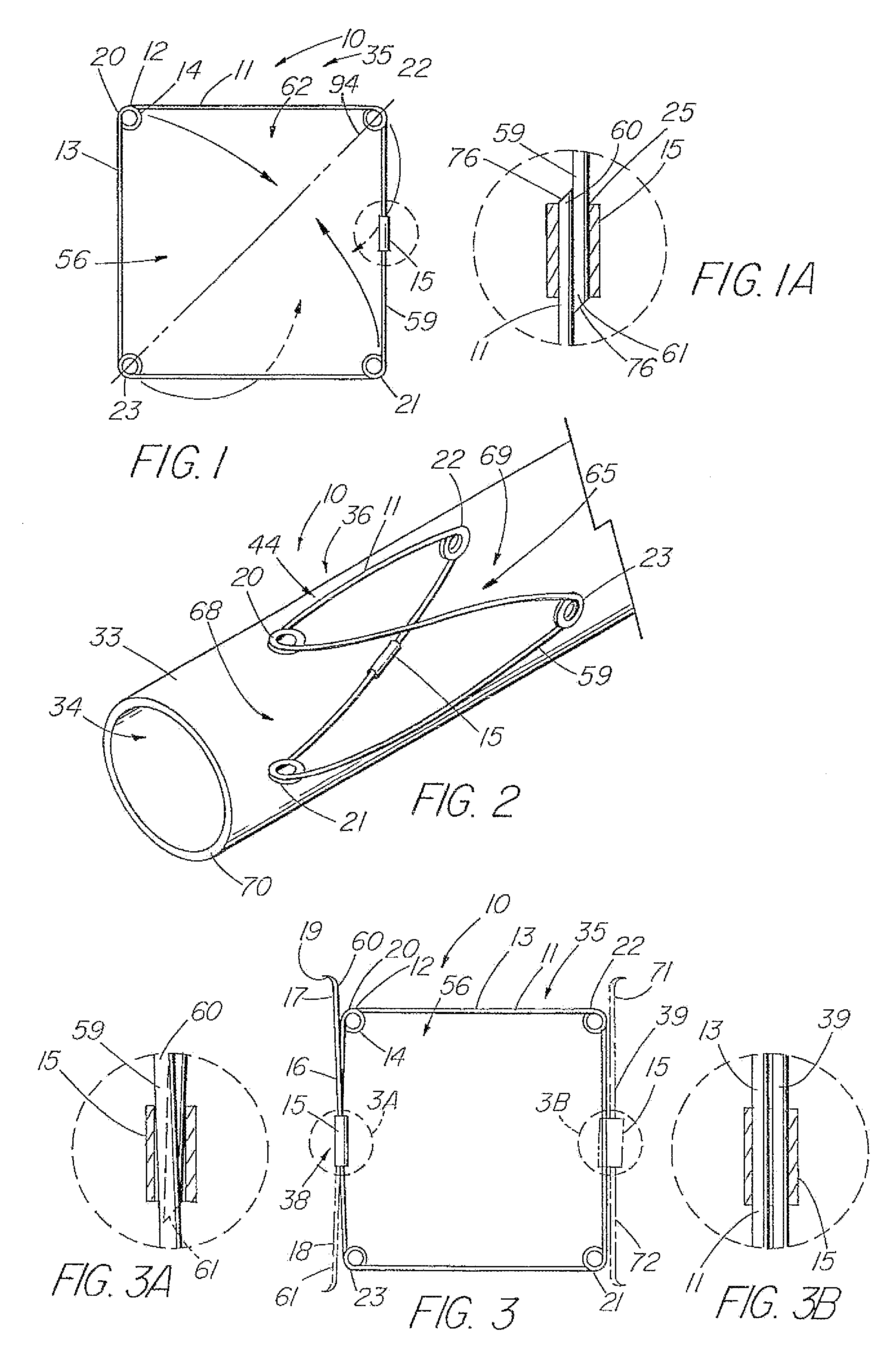
[0118]the present invention is depicted in FIG. 3 wherein one or more barbs 16 are included to anchor the device 10 following deployment. As understood, a barb can be a wire, hook, or any structure attached to the frame and so configured as to be able to anchor the device 10 within a lumen. The illustrative embodiment includes a first barb 16 with up to three other barbs 17,71,72, indicated in dashed lines, representing alternative embodiments. As depicted in detail view A of FIG. 3, the barb combination 38 that comprises barbs 17 and 18, each barb is an extension of the single piece 59 of material of the frame 11 beyond the closed circumference 59. The attachment cannula 15 secures and closes the single piece 59 of material into the frame 11 as previously described, while the first and second ends 60,61 thereof, extend from the cannula 15, running generally parallel with the side 13 of the frame 11 from which they extend, each preferably terminating around or slightly beyond respec...

third embodiment

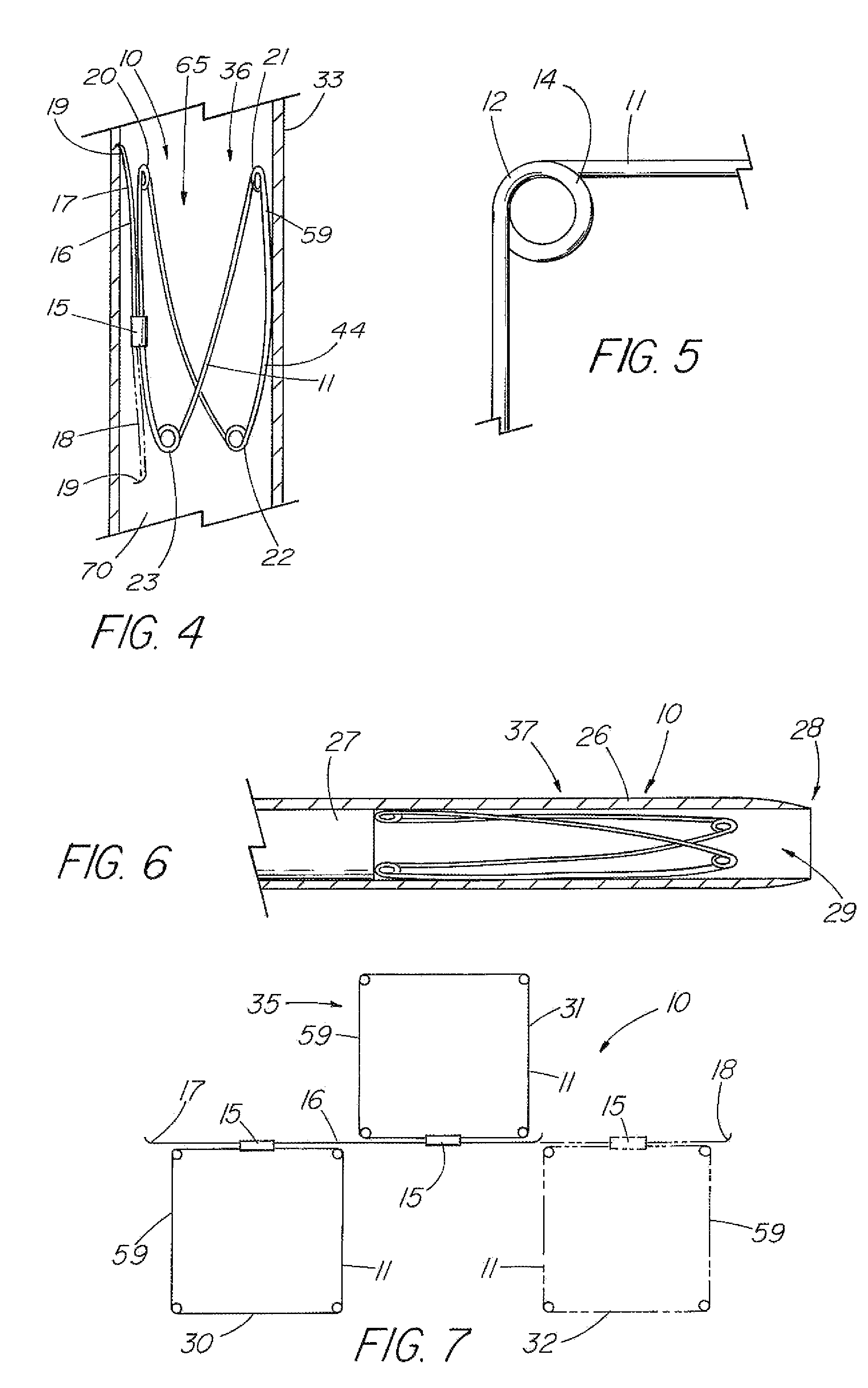
[0120]FIG. 7 depicts a top view of the present invention in the first configuration 35 that includes a plurality of frames 11 attached in series. In the illustrative embodiment, a first frame 30 and second frame 31 are attached by a barb 16 that is secured to each frame by their respective attachment mechanisms 15. The barb 16 can be a double-ended barb 39 as shown in FIG. 3 (and detail view B) that is separate from the single pieces 59 comprising frames 30 and 31, or the barb may represent a long extended end of the one of the single pieces 59 as shown in detail view A of FIG. 3. Further frames, such as third frame 32 shown in dashed lines, can be added by merely extending the length of the barb 16. FIG. 8 depicts a side view of the embodiment of FIG. 7 in the second configuration 36 as deployed in a vessel 33.

fourth embodiment

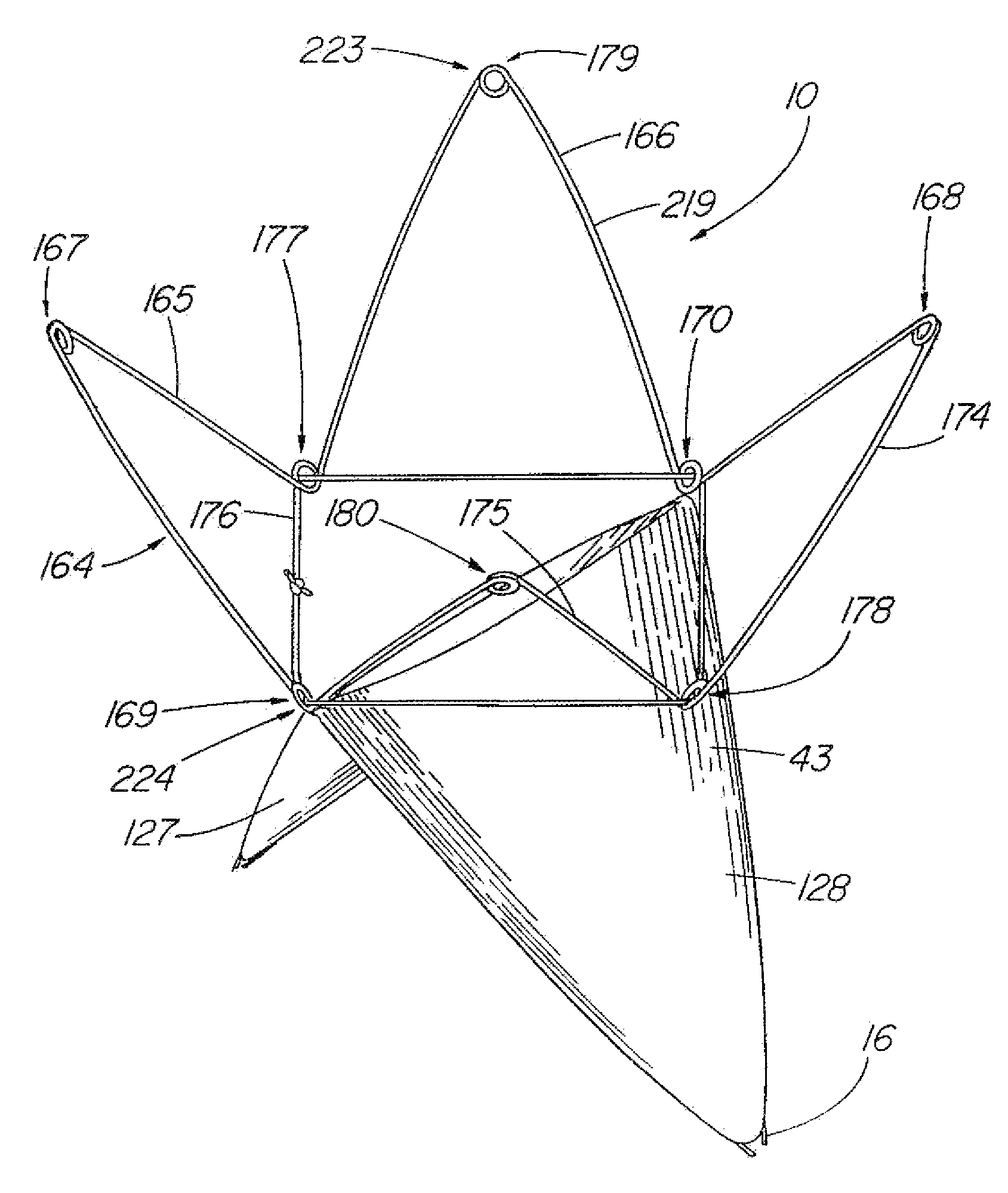
[0121]FIGS. 12-18 depict embodiments of the present invention in which a covering 45 comprising a sheet of fabric, collagen (such as small intestinal submucosa), or other flexible material is attached to the frame 11 by means of sutures 50, adhesive, heat sealing, “weaving” together, crosslinking, or other known means. FIG. 12 depicts a top view of the present invention while in the first configuration 35, in which the covering 45 is a partial covering 58, triangular in shape, that extends over approximately half of the aperture 56 of the frame 11. When formed into the second configuration 36 as shown in FIGS. 13-14, the device 10 can act as an artificial valve 43 such as the type used to correct valvular incompetence. FIG. 13 depicts the valve 43 in the open configuration 48. In this state, the partial covering 58 has been displaced toward the vessel wall 70 due to positive fluid pressure or flow in a first direction 46, e.g., normal venous blood flow, thereby opening a passageway ...


PUM


Abstract

An valve prosthesis, such as an artificial venous valve, having a support frame and leaf structure comprising one or more leaflets in which the outer edge of each leaflet engages the inner circumference of the bodily passageway along a serpentine path urged against the passageway by an expandable frame, while the inner edges move in response to fluid to restrict retrograde flow. Optionally, one or more elements can extend from the support frame / leaf structure to provide centering support and / or protection from the leaflet adhering to the vessel wall. In one embodiment, the centering support structure comprises a second or third expandable frames attached to and extending from the proximal and / or distal ends of main valve structure and support frame. In another embodiment, one or more support elements extend outward from the valve support frame to engage the vessel wall to provide greater longitudinal stability.

Description

RELATED APPLICATIONS[0001]This application is a continuation of U. S. Application Ser. No. 10 / 642,372, filed on Aug. 15, 2003, which claims priority to provisional application Ser. No. 60 / 403,783, filed Aug. 15, 2002, and is a continuation-in-part of application Ser. No. 09 / 777,091, filed Feb. 5, 2001.TECHNICAL FIELD[0002]This invention relates to medical devices, more particularly, to intraluminal devices.BACKGROUND OF THE INVENTION[0003]As minimally invasive techniques and instruments for placement of intraluminal devices have developed over recent years, the number and types of treatment devices have proliferated as well. Stents, stent grafts, occlusion devices, artificial valves, shunts, etc., have provided successful treatment for a number of conditions that heretofore required surgery or lacked an adequate solution altogether. Minimally invasive intravascular devices especially have become popular with the introduction of coronary stents to the U.S. market in the early 1990s. ...

Claims


Application Information

Patent Timeline
Patent Type & Authority Patents(United States)
IPC IPC(8): A61F2/06A61F2/24A61F2/90
CPCA61F2/01A61F2/2418A61F2/2475A61F2/24A61F2230/0069A61F2230/0095A61F2002/8483A61F2230/0054A61F2230/0008A61F2230/001A61F2230/0023A61F2230/0026A61F2230/0058A61F2002/018A61F2/2476
Inventor PAVCNIK, DUSANOSBORNE, THOMAS A.CASE, BRIAN C.FLAGLE, JACOB A.GARRISON, MICHAEL L.PAUL, JR., RAM H.HOFFA, ANDREW K.LEONARD, II, RAYMOND B.SCHAEFFER, DARIN G.SISKEN, RICHARD B.
Owner COOK MEDICAL TECH LLC
Why Eureka
Try Eureka