
Weapon release cable retention device and method

Inactive Publication Date: 2006-12-21
RAYTHEON CO
View PDF6 Cites 12 Cited by
  • Summary
  • Abstract
  • Description
  • Claims
  • Application Information

AI Technical Summary

Benefits of technology

[0009] In accordance with an aspect of the invention, a weapons cable retention device provides a sub

Problems solved by technology

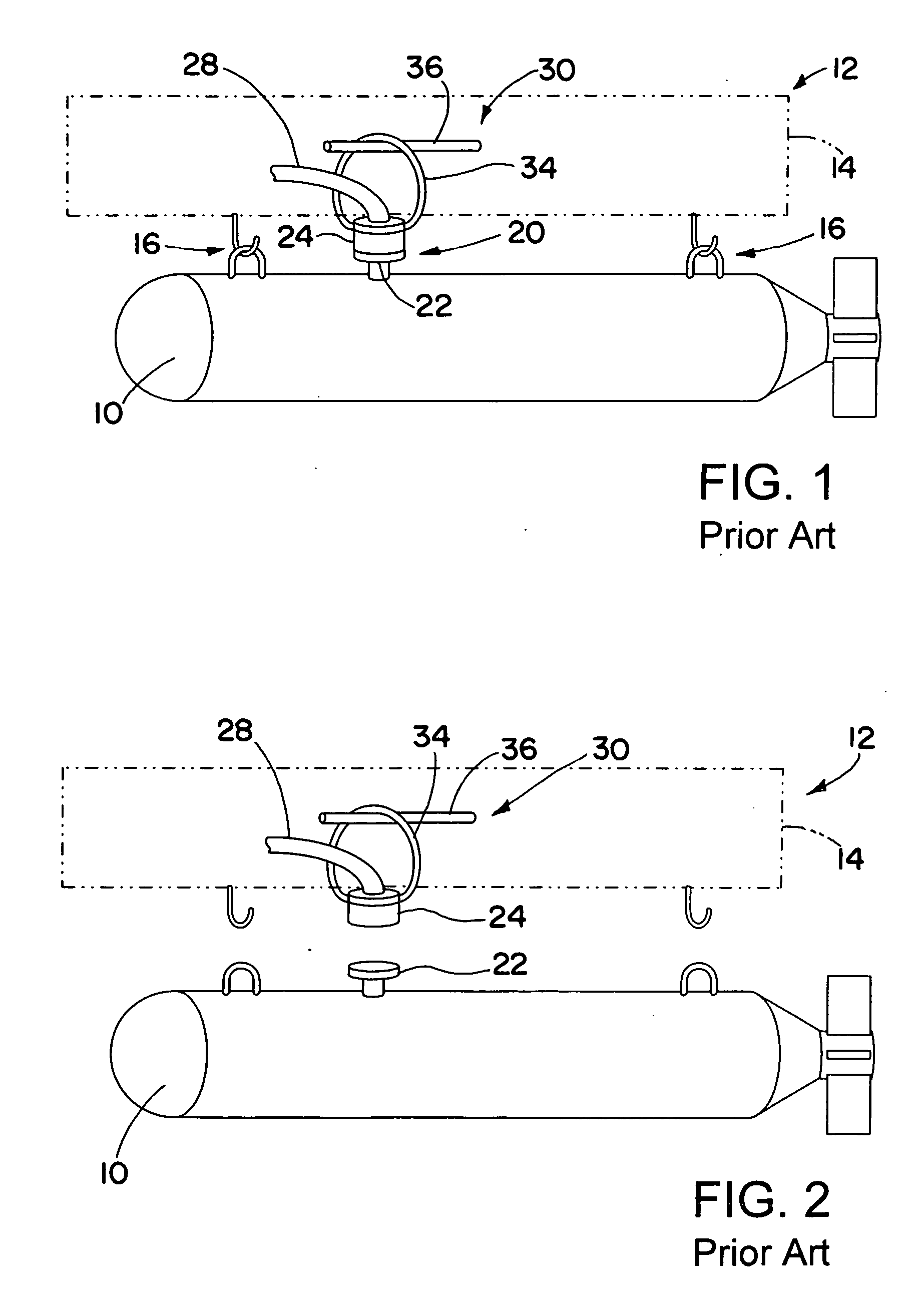
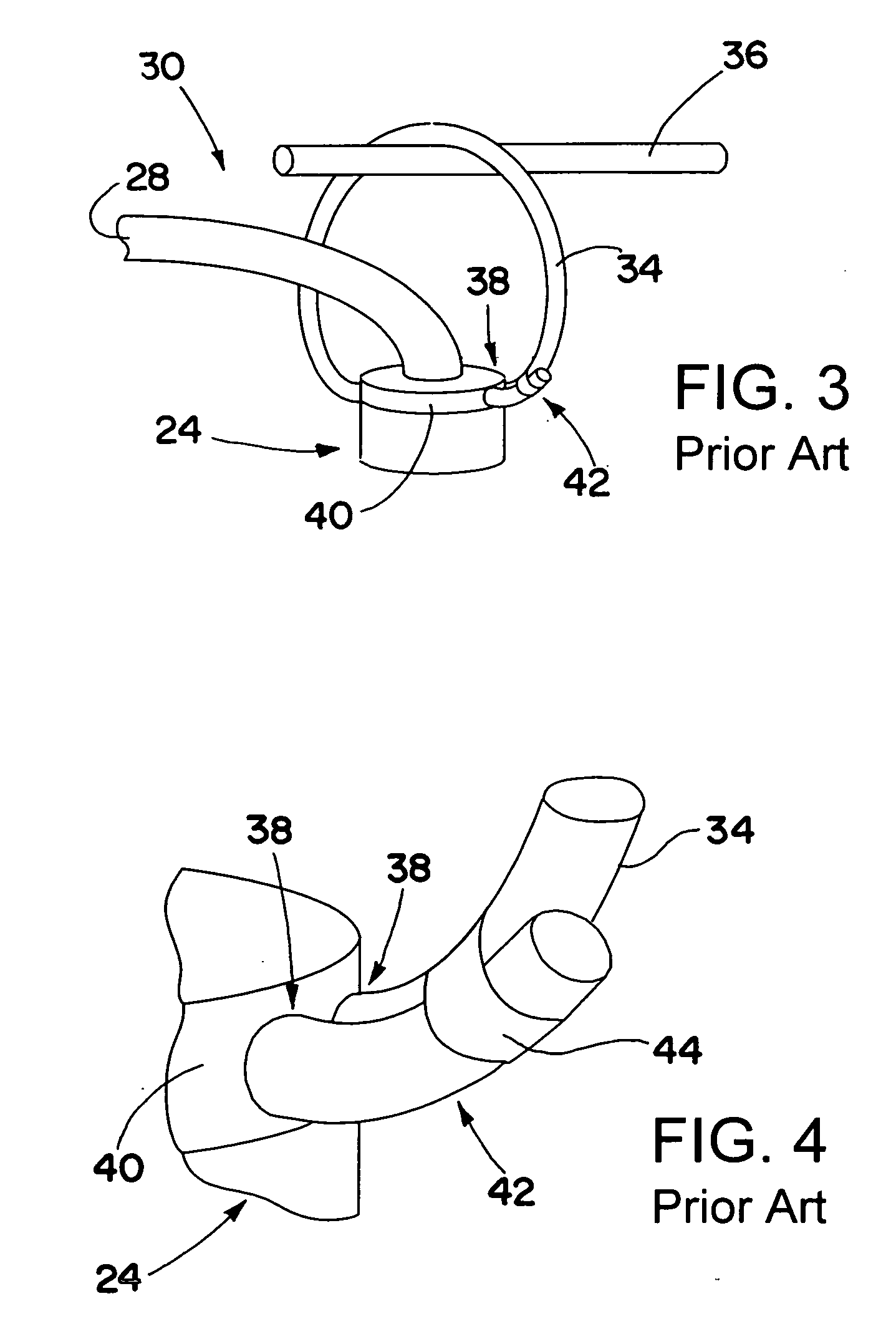
Nevertheless, many problems have been found associated with use of the lanyard 34 to separate the electrical connection 20.
Among these problems are broken or frayed lanyards.
Further, non-uniformities in different releases of the cable retention system 30 may cause different forces to be placed upon the munition 10 during its release, effecting the trajectory of the munition 10.
However, the addition of lanyard reeling devices engenders difficulties because such lanyard reeling devices are considered modifications to the aircraft, which may be difficult to secure approval for use of such devices.
In addition, lanyard reeling device solutions do not control the attitude of the weapons interface connector, during separation of the weapon or munition from the aircraft.

Method used


Image

  • Weapon release cable retention device and method
  • Weapon release cable retention device and method
  • Weapon release cable retention device and method

Examples


Embodiment Construction

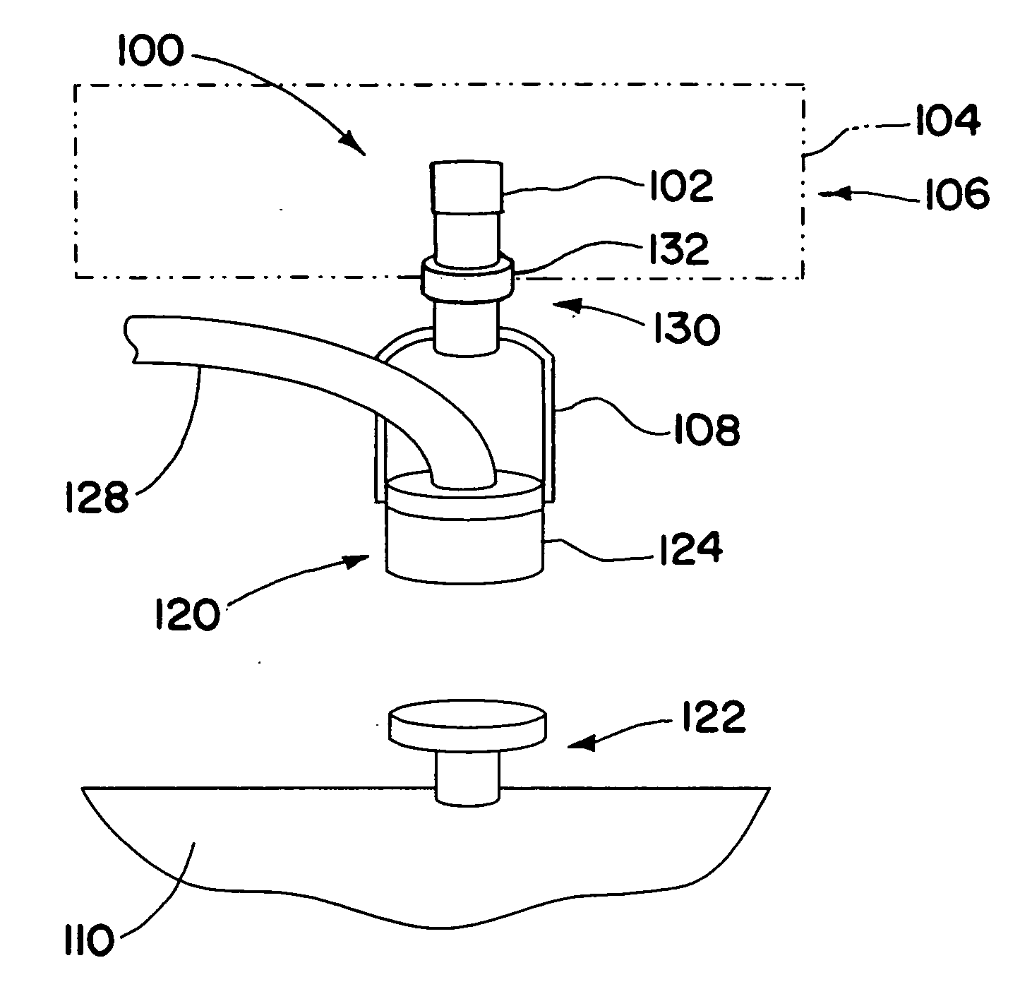
[0029] A weapons cable retention device is used for separating an electrical connection, and retaining a cable and an electrical connector coupled to an aircraft, when a munition, such as a bomb or a missile, is released from the aircraft. The cable retention device includes a structural coupling for coupling to the aircraft, a rod having an adjustment mechanism for adjusting the length of the rod, and an attachment mechanism for attaching to the electrical connector. The cable retention device provides a substantially rigid coupling to secure the electrical connector, thereby reducing variability in release forces on the electrical connector, and increasing the chance of a successful release of the munition, that does not damage the electrical connector and does not unacceptably affect the attitude of the munition. The cable retention device may be configured so that the attachment mechanism engages lanyard holes of a standard electrical connector. According to one embodiment, the ...


PUM


Abstract

A weapons cable retention device is used for separating an electrical connection, and retaining a cable and an electrical connector coupled to an aircraft, when a munition, such as a bomb or a missile, is released from the aircraft. The cable retention device includes a structural coupling for coupling to the aircraft, a rod having an adjustment mechanism for adjusting the length of the rod, and an attachment mechanism for attaching to the electrical connector. The cable retention device provides a substantially rigid coupling to secure the electrical connector. The cable retention device may be configured so that the attachment mechanism engages lanyard holes of a standard electrical connector. According to one embodiment, the structural coupling may include a collar that receives a bail bar on the aircraft structure through a hole therein.

Description

BACKGROUND OF THE INVENTION [0001] 1. Technical Field of the Invention [0002] The invention relates to a device for retaining a cable and electrical connector during release of a weapon, such as a bomb or a missile. [0003] 2. Description of the Related Art [0004] For many types of modern munitions, such as smart bombs, it is desirable to maintain an electrical connection to the munition prior to release of the munition from an aircraft. FIG. 1 illustrates a prior art system and method of making a releasable electrical connection to a munition. A munition 10 is mounted to an aircraft structure 12, such as a pylon 14, by releasable mechanical connections 16 and 18. A releasable electrical connection 20 is also made between a receptacle 22 of the munition, and an electrical connector 24, which is coupled to the electrical system of the aircraft by a cable 28. A cable retention system 30 is used to release the electrical connection 20 when the munition 10 is released from the aircraft s...

Claims


Application Information

Patent Timeline
IPC IPC(8): B64D1/04B64D1/12
CPCB64D1/04F42C19/06F42C14/06F42C11/006
Inventor BLACKBURN, RICK J.
Owner RAYTHEON CO
Learn More