Locking drain filter for floor drains with drain wells

Active Publication Date: 2006-12-21
MCCALLUM BRYAN D
View PDF5 Cites 40 Cited by
  • Summary
  • Abstract
  • Description
  • Claims
  • Application Information

AI Technical Summary

Benefits of technology

[0006] The present invention provides many important technical advantages. One important technical advantage of the present invention is a locking drain filter for floor drains and drain wells that allows a plumber or other personnel that have a need to bypass the filter to readily remove the filter, but which prevent maintenance personnel, cleaning crews, or others that may seek to bypass the drain filter to dispose of materials that can block drain lines from readily removing the filter.

Problems solved by technology

In particular, a locking drain filter for floor drains and drain wells is provided that does not allow the filter to be easily removed by maintenance or cleaning crews, but which allows suitable authorized persons to remove the filter.

Method used


Image

  • Locking drain filter for floor drains with drain wells
  • Locking drain filter for floor drains with drain wells
  • Locking drain filter for floor drains with drain wells

Examples


Embodiment Construction

[0010] In the description that follows, like parts are marked throughout the specification and drawings with the same reference numerals, respectively. The drawing figures might not be to scale, and certain components can be shown in generalized or schematic form and identified by commercial designations in the interest of clarity and conciseness.

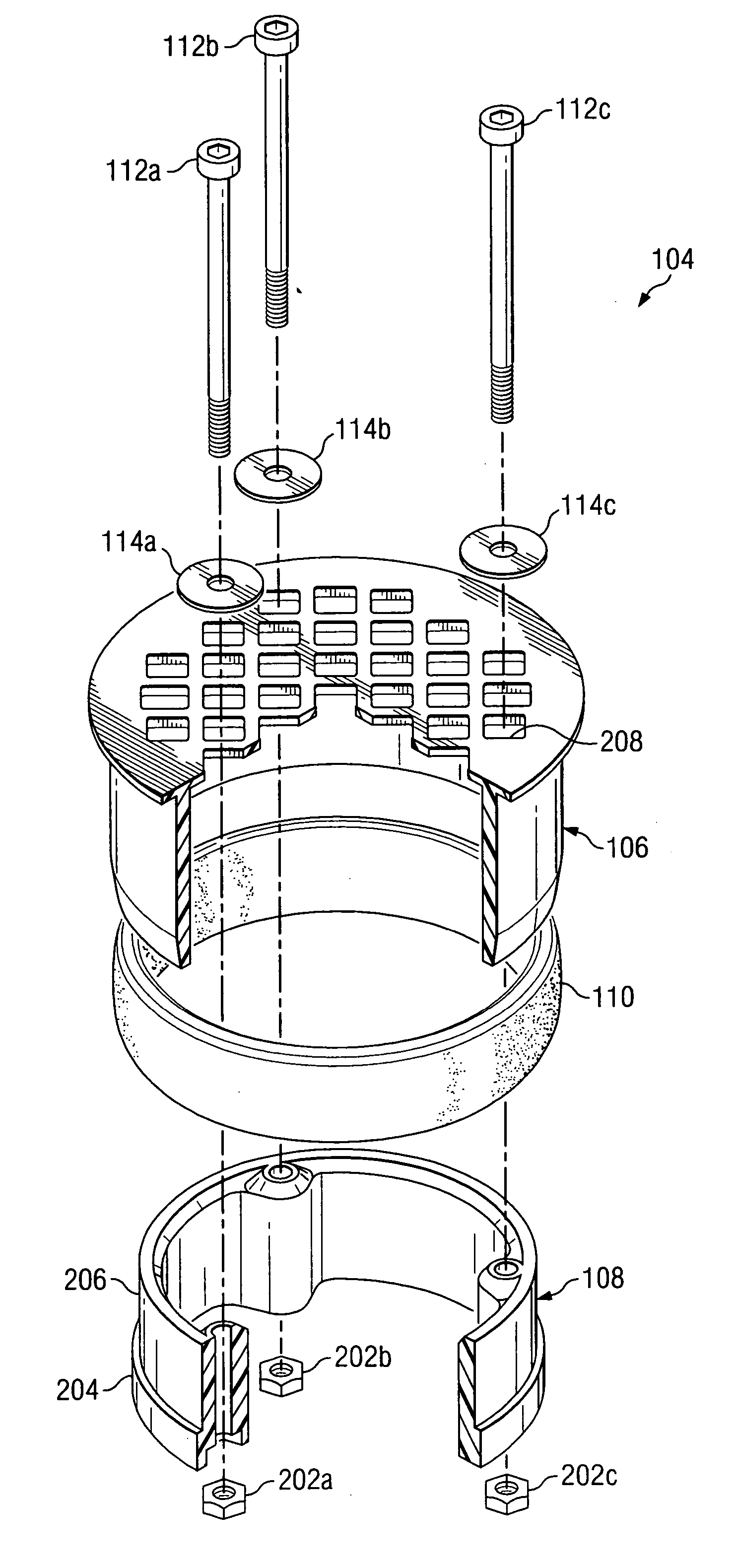
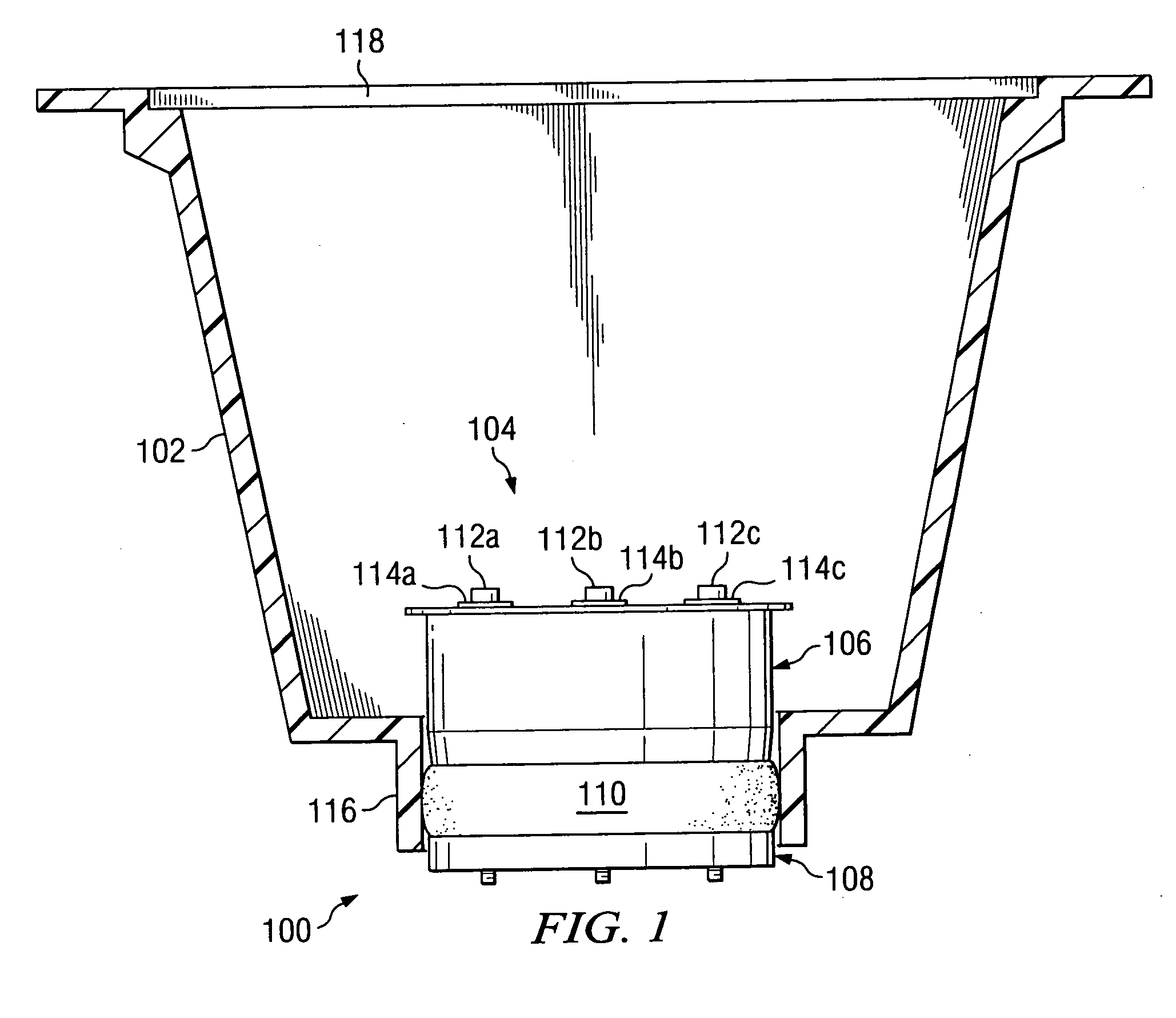
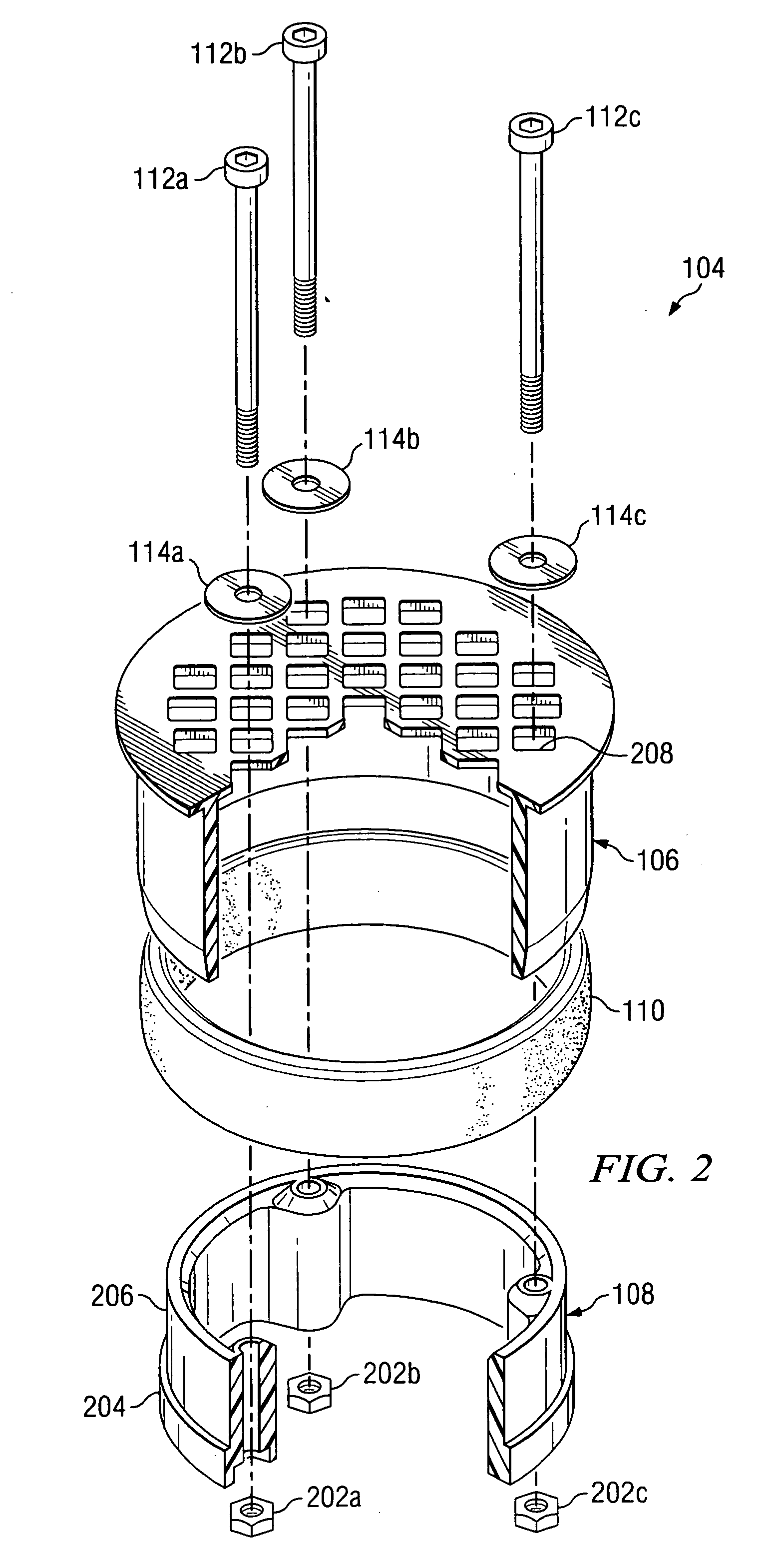
[0011]FIG. 1 is a diagram of a drain apparatus 100 in accordance with an exemplary embodiment of the present invention. Drain apparatus 100 can be used in conjunction with floor drains, floor sinks, trough drains, or other suitable structures, and includes a removable filter 104 that is not readily removable by personnel other than those that have been approved to remove filter 104.

[0012] Drain apparatus 100 includes drain well 102, which can be formed from polyvinyl chloride, (PVC), plastic, metal, or other suitable materials. Drain well 102 allows water or other fluids to collect to drain through filter 104 into drain 116, so as to be r...


PUM

PropertyMeasurementUnit
external dimensionsaaaaaaaaaa
compressive forceaaaaaaaaaa
forceaaaaaaaaaa

Abstract

A locking drain filter for floor drains with drain wells is provided. An upper filter portion has external dimensions that allow the upper filter portion to be inserted into a drain line at the bottom of the drain well. A lower filter portion has first external dimensions that allow the lower filter portion to be inserted into the drain line and second external dimensions that allow the lower filter portion to be inserted into the upper filter portion. A compressible gasket has external dimensions that allow the compressible gasket to be inserted into the drain line when the compressible gasket is in an uncompressed state and internal dimensions that allow the compressible gasket to be placed over the second external dimensions of the lower filter portion. A compression device applies a compressive force to the upper filter portion and the lower filter portion, and if the upper filter portion, compressible gasket, and lower filter portion have been inserted into the drain line prior to the application of the compressive force, the compressible gasket is compressed by the upper filter portion and the lower filter portion and expands radially so as to lock the upper filter portion and the lower filter portion into the drain line.

Description

FIELD OF THE INVENTION [0001] The present invention pertains to the field of plumbing equipment, and more particularly to a locking drain filter for floor drains with drain wells, such as those commonly used in the restaurant and food processing industries. BACKGROUND OF THE INVENTION [0002] Floor drains are widely used in restaurants, food processing facilities, and other light industrial facilities where water or other fluids may accumulate in significant volumes on the floor of the facility. For example, such floor drains typically include a cover that provides a grate or other water permeable barrier to prevent entry into the drain of items that can block the drainage pipes, and a drain well underneath the barrier to allow the water or other fluids to accumulate in the well if they are accumulating faster than the drain pipe can remove them, as well as to prevent the water or fluids from flowing away from the drain before they have a chance to be removed from the local environme...

Claims


Application Information

Patent Timeline
Patent Type & Authority Applications(United States)
IPC IPC(8): B01D24/00
CPCE03F1/00Y10T29/49826E03F5/0404
Inventor MCCALLUM, BRYAN D.
Owner MCCALLUM BRYAN D
Why Eureka
Try Eureka