Method of forming monodisperse bubble

a monodisperse bubble and bubble technology, applied in the field of monodisperse bubble production, can solve the problems of difficult to produce very fine bubbles with bubble diameters on the order of nanometers, impaired stability, and extremely difficult in the above-mentioned methods to freely adjust the bubble diameter

Inactive Publication Date: 2006-12-21
MIYAZAKI PREFECTURE +1
View PDF8 Cites 33 Cited by
  • Summary
  • Abstract
  • Description
  • Claims
  • Application Information

AI Technical Summary

Benefits of technology

[0017] The method according to the present invention can reliably produce highly monodisperse bubbles. The method according to the present invention in particular can also provide microfine monodisperse bubbles for which the bubble diameter size is in the nanometer range (monodisperse nanobubbles). In addition, the method according to the present invention also enables the bubble diameter to be freely adjusted by varying, for example, the pore diameter of the porous body.
[0018] The monodisperse bubbles an

Problems solved by technology

However, these methods, excluding methods that generate microfine bubbles utilizing microwaves, not only have difficulty producing very fine bubbles with bubble diameters on the order of nanometers, but

Method used


Image

  • Method of forming monodisperse bubble
  • Method of forming monodisperse bubble
  • Method of forming monodisperse bubble

Examples


example 1

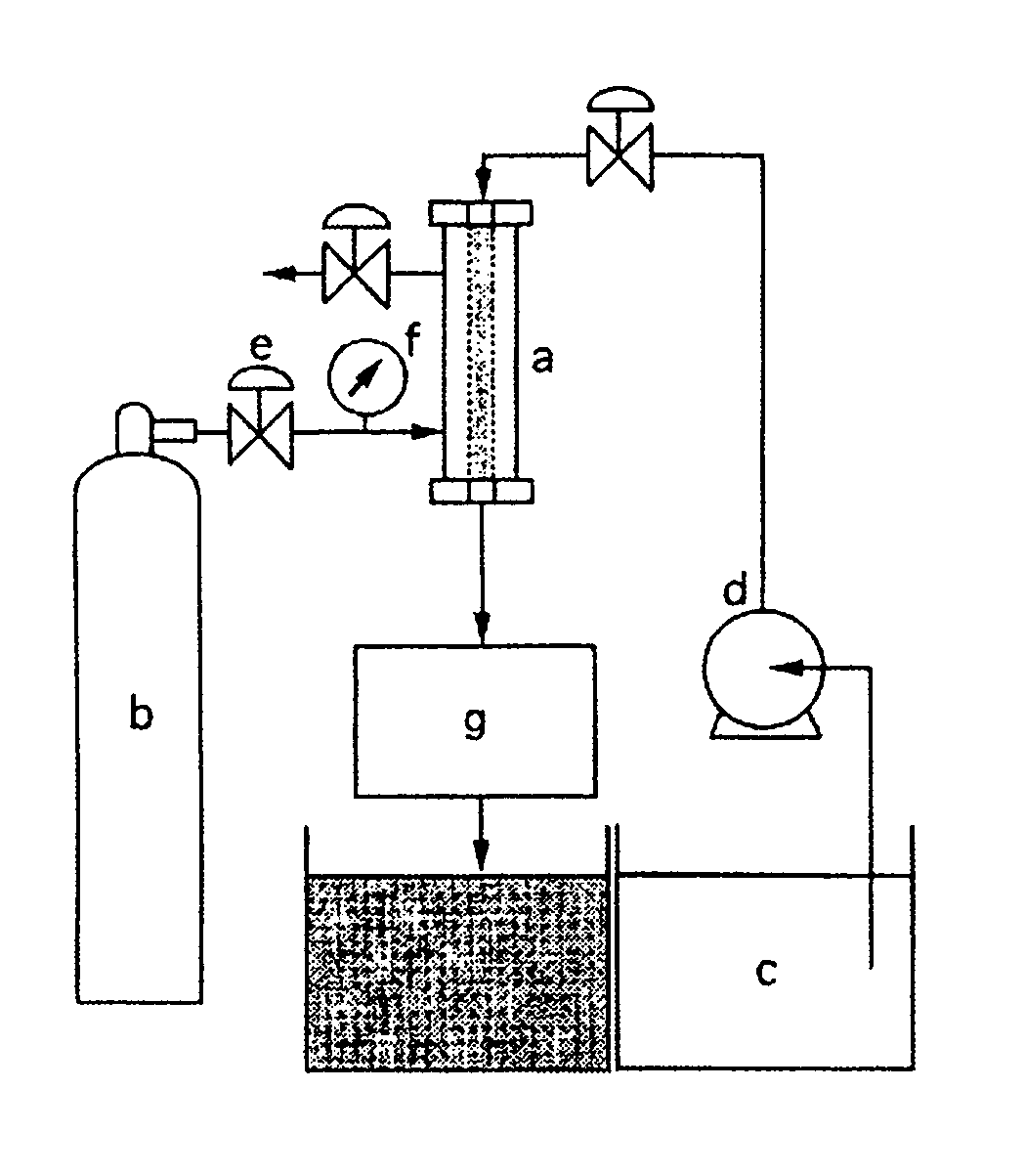
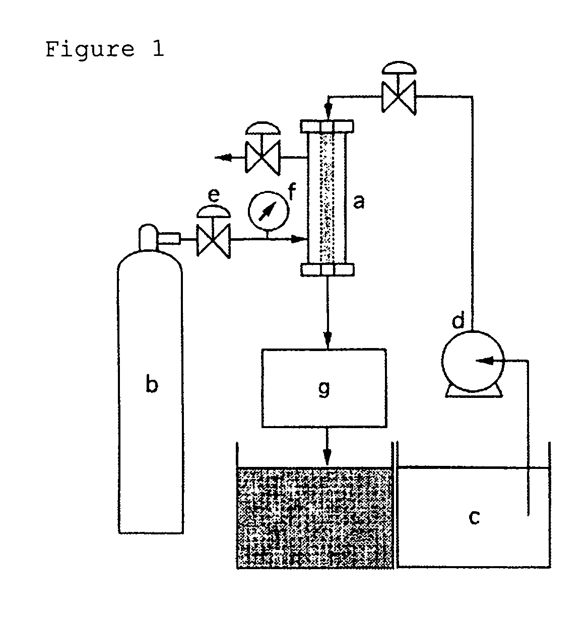
[0063] Using the apparatus shown in FIG. 1, air was injected and dispersed through a tubular porous glass membrane having an average pore diameter of 85 nm (SPG membrane from SPG Technology Co., Ltd.) into an aqueous solution containing 0.1 weight % anionic emulsifying agent (sodium dodecyl sulfate). The pressure differenceΔP between the air and the aqueous solution was 3.0 MPa and the liquid temperature was 25° C. The aqueous solution was transported by a pump and the in-tube flow velocity within the membrane was set at 4.0 m / s.

[0064] The generated bubbles were directly introduced into the measurement cell of a particle diameter distribution measurement instrument (product name: “SALD2000”, from the Shimadzu Corporation). The obtained bubble diameter distribution is shown in FIG. 3. As is clear from FIG. 3, the obtained bubbles were highly monodisperse nanobubbles having an average bubble diameter of 750 nm.

example 2

[0065] The relationship between the pore diameter of the porous glass membrane and the average bubble diameter of the generated bubbles was investigated in accordance with Example 1 by varying the average pore diameter of the porous glass membrane. The results are shown in FIG. 4. As is clear from FIG. 4, a linear relationship given by Dp=8.6 Dm exists between the average bubble diameter Dp and the average pore diameter Dm.

example 3

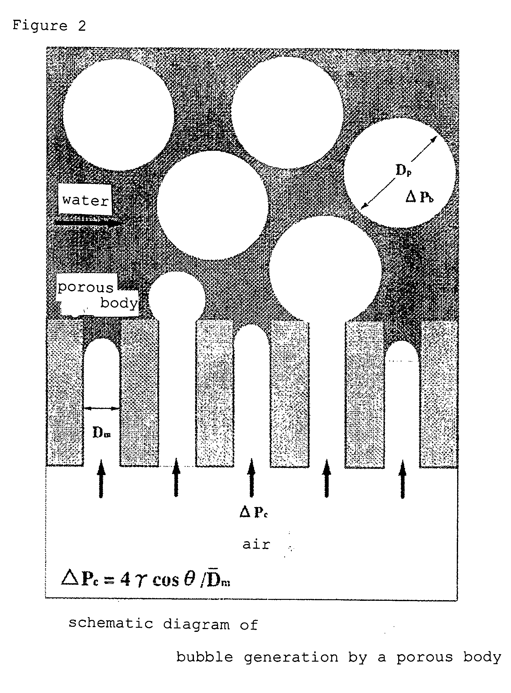
[0066] The relationship for the minimum pressure ΔPc (critical pressure) at which bubble generation began for different average pore diameters in the porous glass membrane was investigated in accordance with Example 1 by varying the average pore diameter of the porous glass membrane. The results are shown in FIG. 5. The relationship between ΔP and Dm was in approximate agreement with the equation shown above by (1) ΔP=4γ cos θ / Dm.


PUM

PropertyMeasurementUnit
Fractionaaaaaaaaaa
Fractionaaaaaaaaaa
Fractionaaaaaaaaaa

Abstract

The invention provides a method for producing bubbles that exhibit an excellent monodispersity. The invention relates to a method for generating bubbles by the injection and dispersion of a gas through a porous body into a liquid, wherein the value produced by dividing the pore diameter that accounts for 10% of the total pore volume in the relative cumulative pore distribution curve of the porous body by the pore diameter that accounts for 90% of the total pore volume in the relative cumulative pore dismeter distribution curve of the porous body is 1 to 1.5.

Description

TECHNICAL FIELD [0001] The present invention relates to a method for producing monodisperse bubbles. BACKGROUND ART [0002] Various methods for generating bubbles have already been proposed. Examples in this regard are a) gas transport methods in which a gas is passed through the micropores of a gas dispersing tube into a liquid; b) methods in which a vibration with a frequency no greater than 1 kHz is applied to a porous body while a gas is being fed into a liquid through the porous body; c) bubble generation methods that utilize ultrasound; d) shaking·stirring methods in which bubbles are generated by stirring a liquid and shearing a gas; e) methods in which a gas is dissolved under pressure in a liquid followed by pressure reduction in order to generate bubbles from the supersaturated dissolved gas; and f) chemical foaming methods in which bubbles are created by generating a gas in a liquid by a chemical reaction (refer, for example, to Clift, R. et al., “Bubbles, Drops, and Parti...

Claims


Application Information

Patent Timeline
IPC IPC(8): B01F3/04B01F23/00
CPCY10S261/26B01F3/04262B01F23/23123B01F23/00B01F23/20
Inventor KOHAMA, YASUAKIKUKIZAKI, MASATONAKASHIMA, TADAO
Owner MIYAZAKI PREFECTURE
Why Eureka
Try Eureka