Error compensation for a wireless sensor using a rotating microstrip coupler to stimulate and interrogate a saw device

Inactive Publication Date: 2006-12-21
HONEYWELL INT INC
View PDF13 Cites 14 Cited by
  • Summary
  • Abstract
  • Description
  • Claims
  • Application Information

AI Technical Summary

Benefits of technology

[0012] The following summary is provided to facilitate an understanding of some of the innovative features unique to the embodiments and is not intended to be a full

Problems solved by technology

Forcing a spinning plate's face against another plate's face causes power transfer or loss at the interface.
As such, the errors in the power measurement are many multiples higher than those in the torque sensor.
The relative rotational displacement, also called the angular offset, between cer

Method used


Image

  • Error compensation for a wireless sensor using a rotating microstrip coupler to stimulate and interrogate a saw device
  • Error compensation for a wireless sensor using a rotating microstrip coupler to stimulate and interrogate a saw device
  • Error compensation for a wireless sensor using a rotating microstrip coupler to stimulate and interrogate a saw device

Examples


Example

[0028] The particular values and configurations discussed in these non-limiting examples can be varied and are cited merely to illustrate at least one embodiment and are not intended to limit the scope thereof. In general, the figures are not to scale.

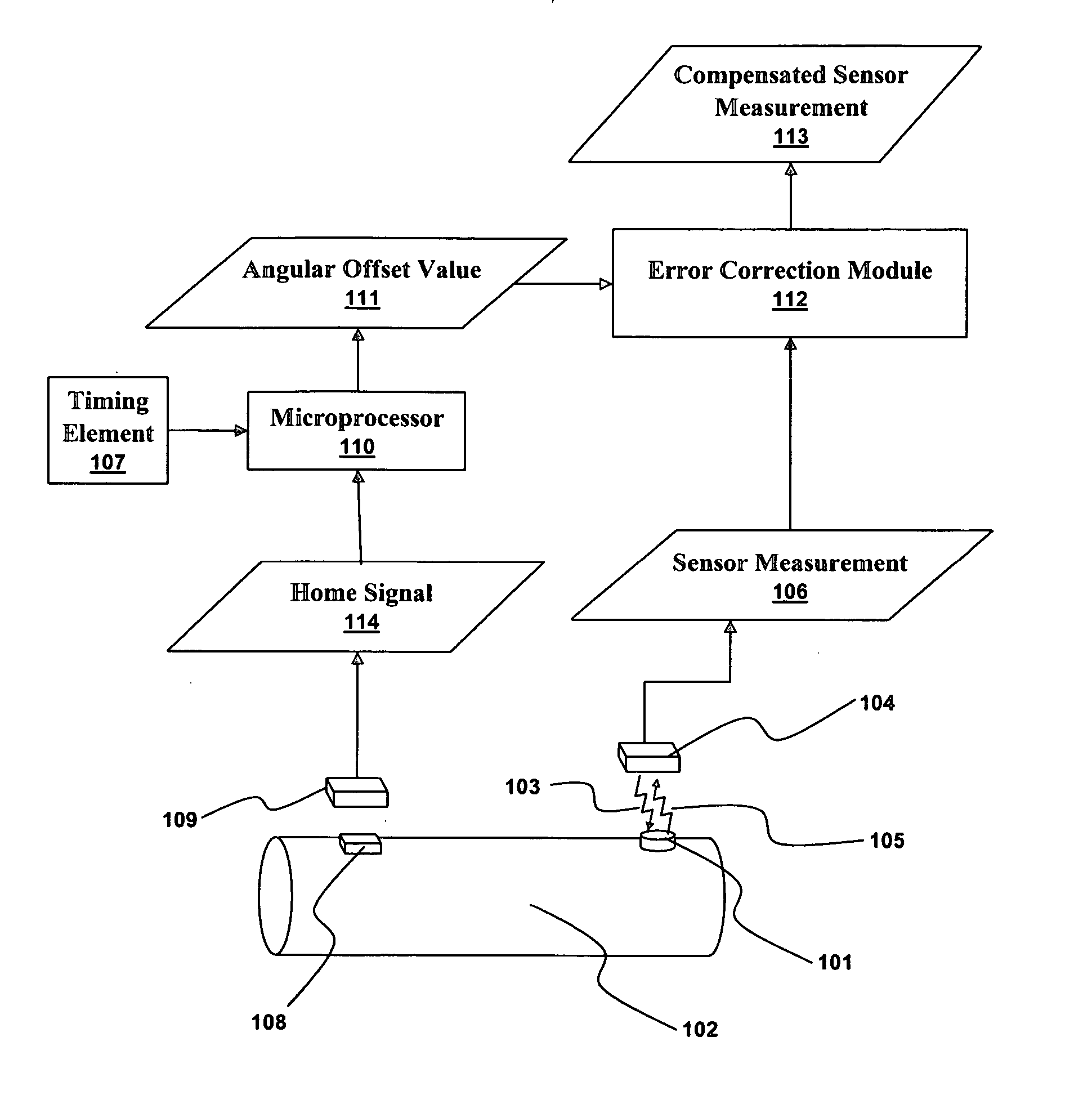
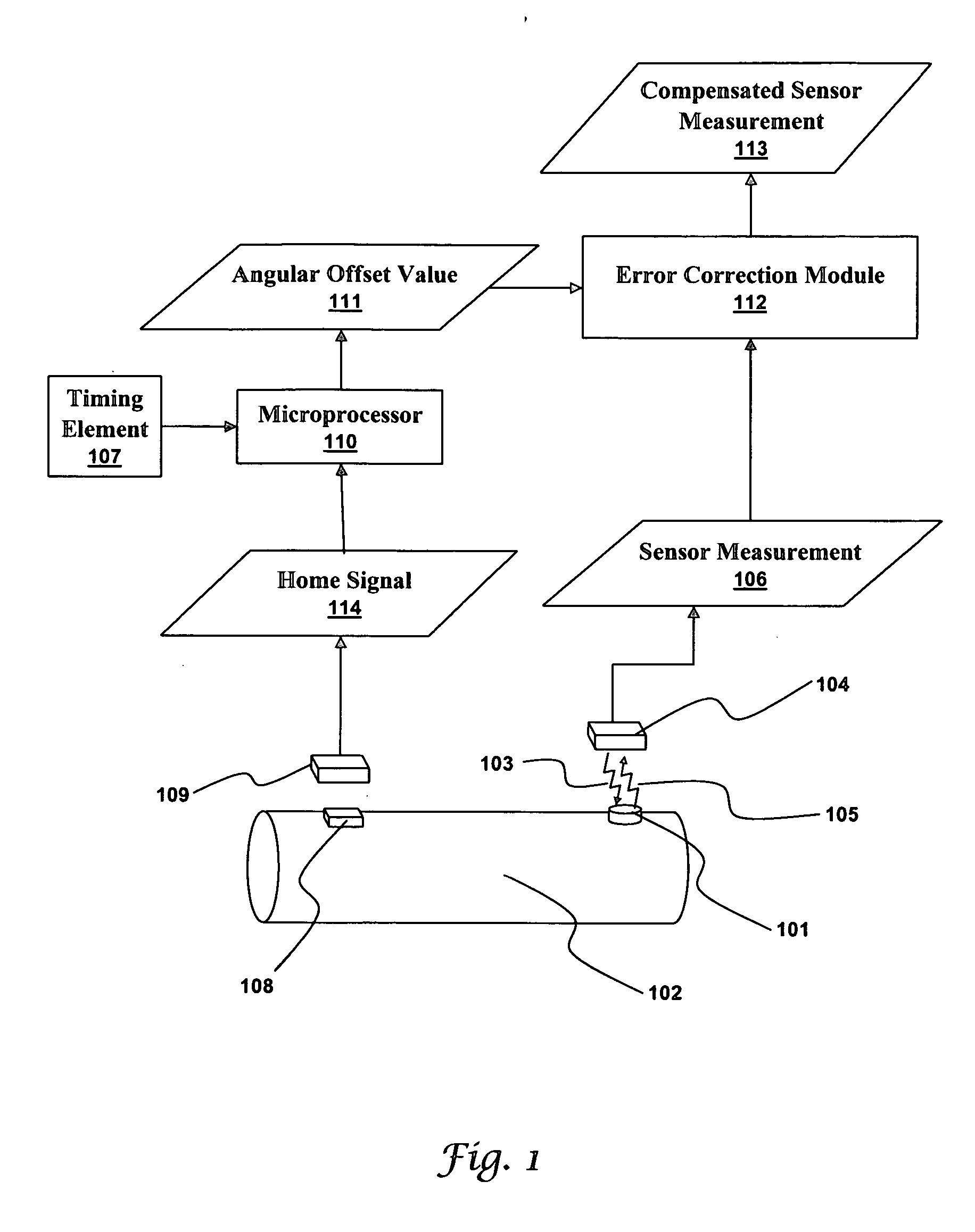
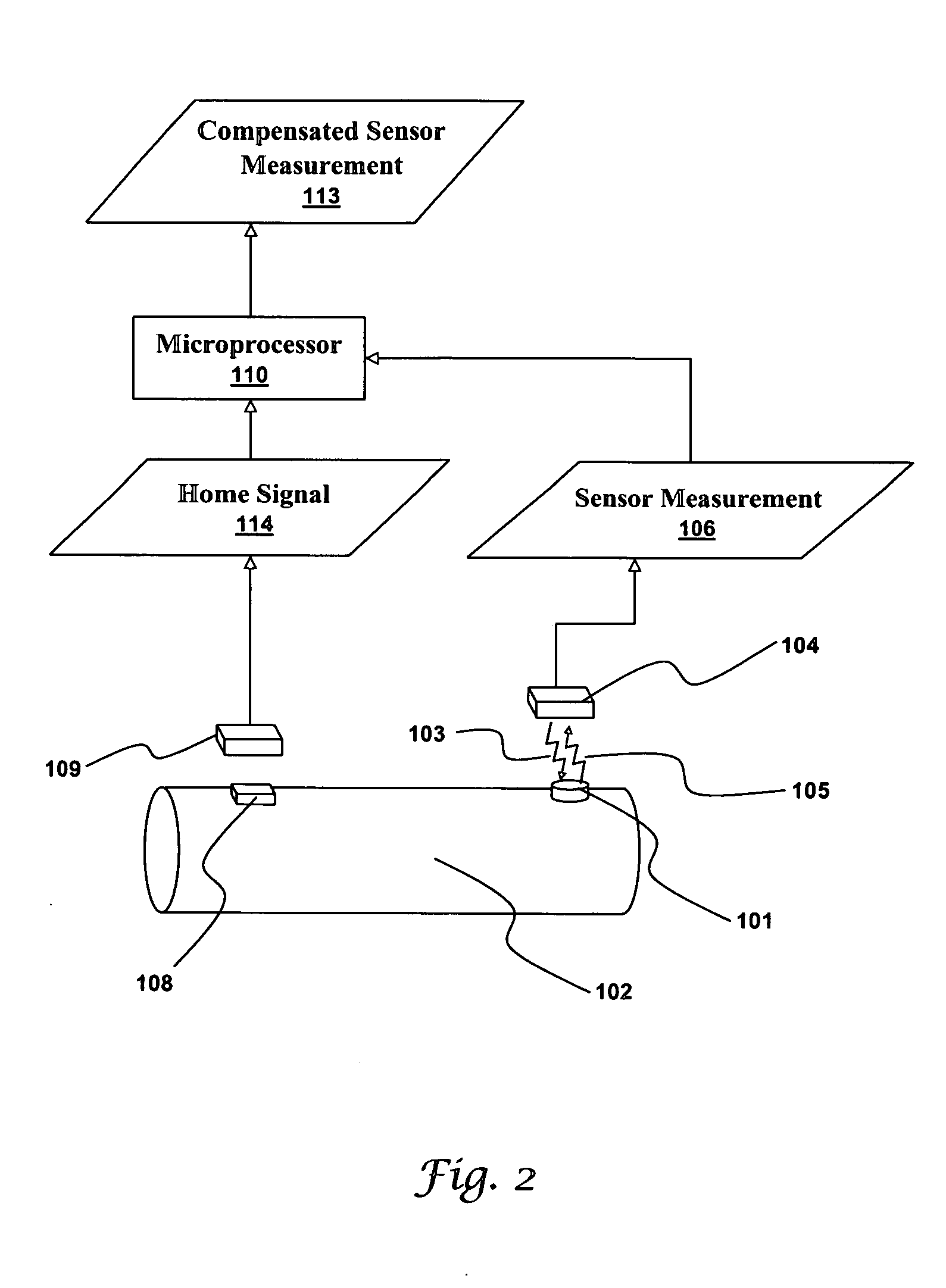
[0029]FIG. 1 illustrates a system producing a compensated sensor measurement 113 in accordance with an embodiment. A passive wireless sensor 101 is attached to a rotating element 102. A stationary circuit 104 creates an electromagnetic field 103 that energizes the passive wireless sensor 101. Here, the electromagnetic field 103 is shown as a ragged arrow to indicate the sensor it is energizing. In practice, electromagnetic fields a rarely highly directional. The passive wireless sensor 101, once energized, produces a sensor signal 105 that is transmitted back to the stationary circuit 104. The sensor signal 105 contains a sensor measurement 106. As discussed above, a read error based on the angular offset between the passive wireless ...


PUM


Abstract

Many mechanical systems contain rotating parts used to transfer power from one part of the system to another. The system's efficiency and longevity can be increased by measuring the speed and loading of the rotating parts. Passive wireless sensors are ideal for instrumenting rotating parts because they require no connecting wires and no stored energy. The sensor measurements contain read errors when the stationary interrogation circuit and the rotating sensor are not ideally aligned. The read errors are a function of the angular offset between the stationary interrogation circuit and the passive sensor. As such, the read errors are deterministic. A measurement of the angular offset between the stationary interrogation circuit and the passive sensor is used to determine a correction factor that cancels out the read error to produce a compensated sensor signal.

Description

CROSS-REFERENCE TO RELATED APPLICATION [0001] This patent application is a Continuation-in-Part (CIP) of U.S. patent application Ser. No. 11 / 156,171, entitled “Speed Sensor for a Power Sensor Module,” which was filed on Jun. 16, 2005 and is incorporated herein by reference in its entirety.TECHNICAL FIELD [0002] Embodiments relate to mechanical power sensing and mechanical power measurement. Embodiments also relate to passive wireless sensors, SAW sensors, angular position sensing, and error compensation. BACKGROUND OF THE INVENTION [0003] Machinery must often apply power generated by an engine or motor to a purpose such as drilling a hole or turning a wheel. As such, the machinery must transfer mechanical power. Mechanical power is transferred by rotating elements such as shafts, plates, and gears. For example, in a car the power generated by the engine must be transferred to the wheels. Most car engines generate power that is available on a rotating shaft called the crankshaft. The...

Claims


Application Information

Patent Timeline
IPC IPC(8): H02P7/00
CPCG01L3/106G01L25/003
Inventor ANDREWS, RICHARD M.BUNYER, SCOTT L.HINTZ, FRED W.LIU, JAMES ZTMAGEE, STEVEN J.O'BRIEN, GARY
Owner HONEYWELL INT INC
Why Eureka
Try Eureka