Autostereoscopic display with planar pass-through

a technology of autostereoscopic display and planar pass-through, which is applied in the field of electronic autostereoscopic flat panel display, can solve the problems of inability to achieve the planar mode usefulness, performance is unacceptable, and the effective resolution of the display when planar data is viewed, and achieves the effect of enhancing the planar image data

Inactive Publication Date: 2006-12-21
REAID INC
View PDF6 Cites 128 Cited by
  • Summary
  • Abstract
  • Description
  • Claims
  • Application Information

AI Technical Summary

Benefits of technology

[0016] According to one aspect of the present design, there is provided a method for presenting both autostereoscopic images and planar images in a single display. The method comprises processing the planar images received in the form of planar image data. The processing comprises at least one from a group comprising selectively employing bleed-through processing to enhance the planar image data when viewed through a lens sheet comprising slanted lenticules, selectively introducing blurring into the planar image data, and selectively employing anti-alias processing to the planar image data.

Problems solved by technology

The problem that faces the designer is that the microlens array, with its multiplicity of refractive elements, while producing an autostereoscopic image in association with properly encoded or mapped data, will reduce the effective resolution of the display when planar data is viewed.
The usefulness in the planar mode is so compromised that performance is unacceptable.
In addition, many users find storing the lens sheet inconvenient.
Both storage and alignment are factors of concern, and the solution is somewhat inelegant.
However, the process of placing and removing the lens sheet is hardly transparent to the user and generally inconvenient.
In present designs, the Sharp device uses only two views and suffers from a tiny viewing zone, which is very undesirable.
The Sharp design uses two liquid cells in optical series, has the disadvantage of increased cost, and suffers from reduced brightness.
For the reasons given above, previously available displays may not be entirely practical in terms of price and performance.

Method used


Image

  • Autostereoscopic display with planar pass-through
  • Autostereoscopic display with planar pass-through
  • Autostereoscopic display with planar pass-through

Examples


Embodiment Construction

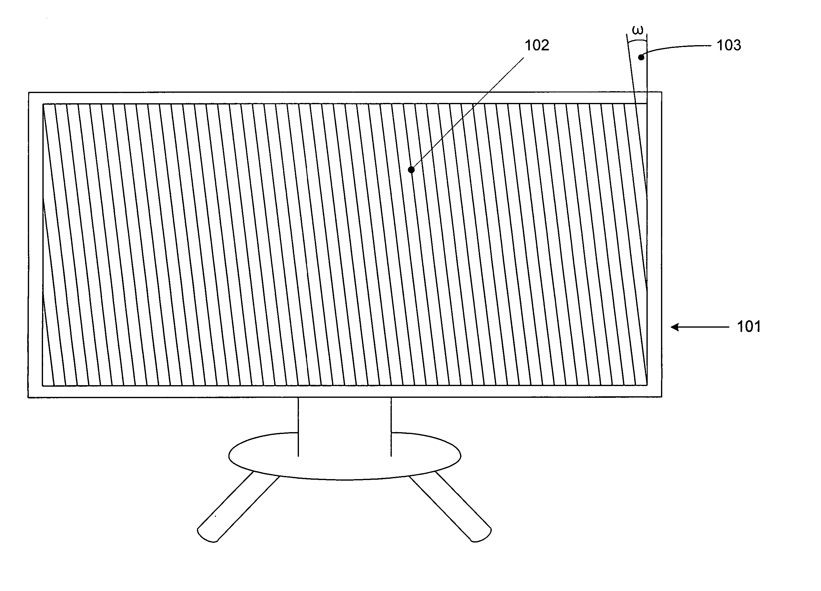
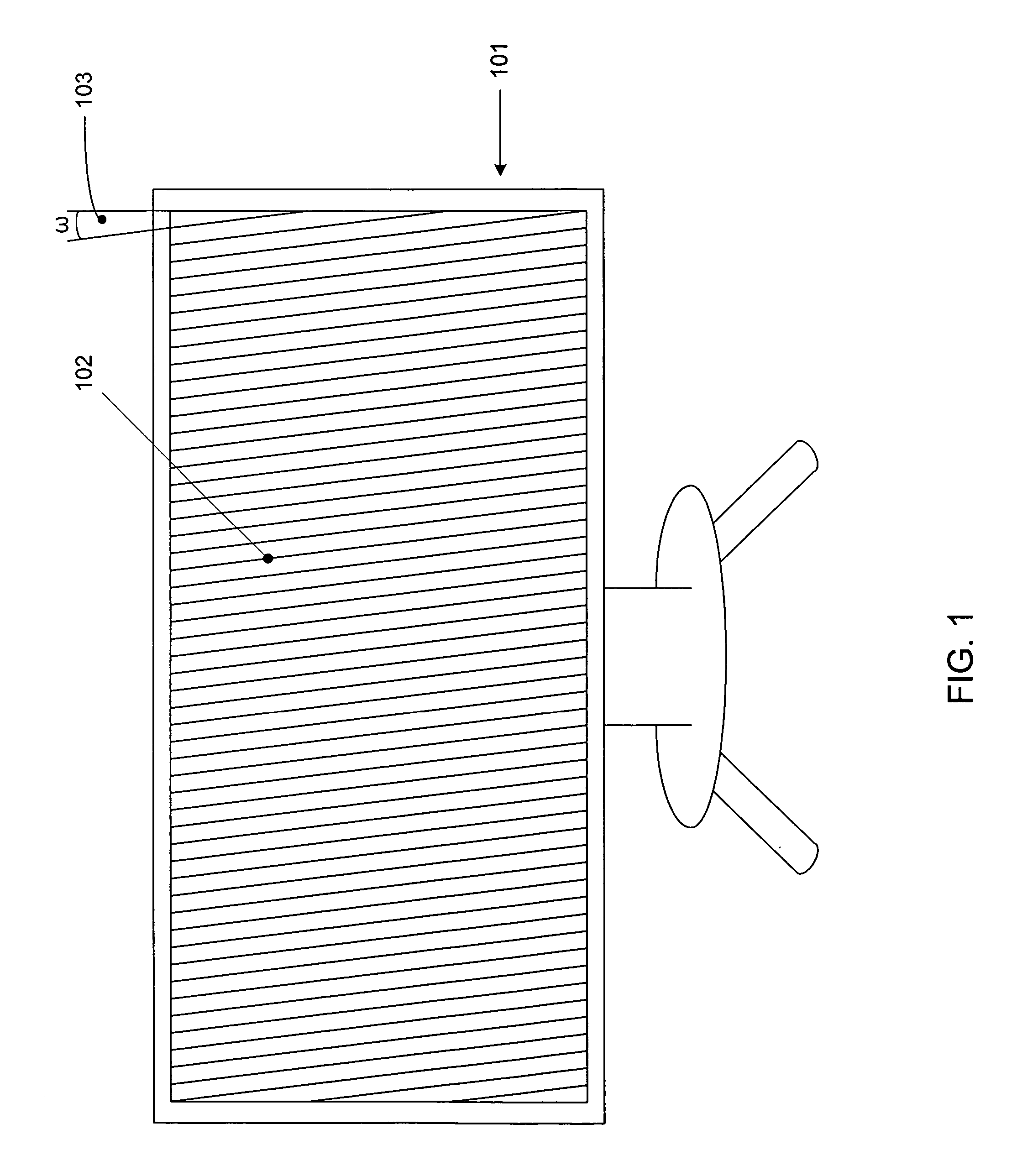
[0027] The present design comprises a combination of optical and software techniques providing a low cost device for passing a high quality planar image through the microlens array of an autostereoscopic display. The transition from one mode to the other will be automatic and transparent to the user. As used in this description, the technology to pass a quality image to the user is called “planar pass-through” or simply “pass-through.”

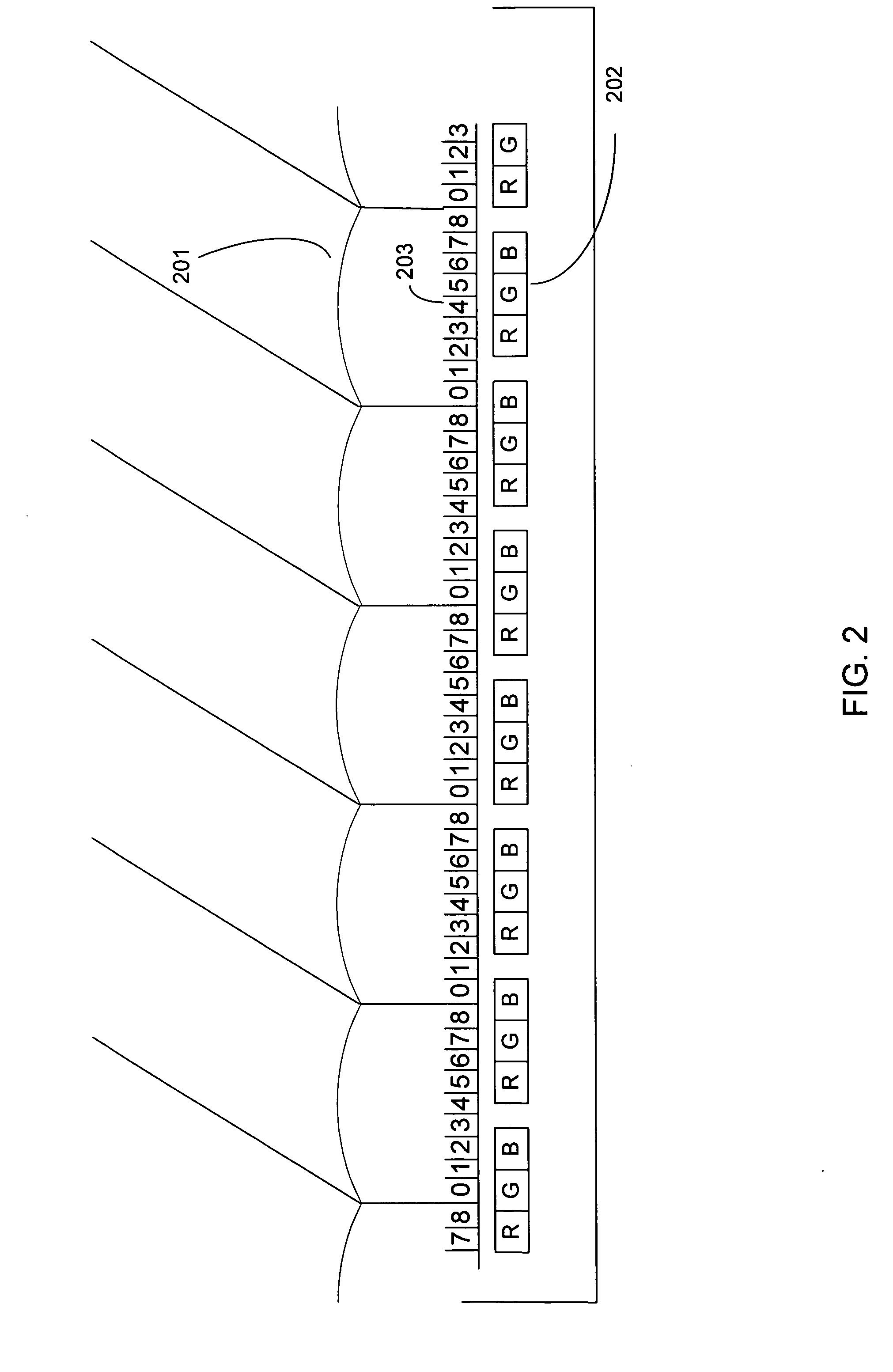
[0028] Any flat panel display has a “native resolution”, by which is meant the actual pixel count in the horizontal and vertical dimensions. Flat panel displays, unlike their CRT precursors, have a fixed resolution capability and rely on image scaling in order to match a variety of resolution images to the display. The microlens array serves to modulate the native resolution of the flat panel display, while enabling stereoscopic capability, effectively reducing resolution for planar applications.

[0029] The lenslets of the microlens array or lens sheet...


PUM


Abstract

A method and system for presenting both autostereoscopic images and planar images in a single display is disclosed. The design comprises processing the planar images received in the form of planar image data. The processing comprises at least one from a group comprising selectively employing bleed-through processing to enhance the planar image data when viewed through a lens sheet comprising slanted lenticules, selectively introducing blurring into the planar image data, and selectively employing anti-alias processing to the planar image data. Certain super pixels may be computed that differ from standard pixels, and lenticules in the data sheet may be slanted at desired angles. The physical lenticules may cause bleed-through that may be processed. Resolution may be computed after processing, and the resolution implemented for display. Mode switching between planar and autostereoscopic imaging may be provided in the form of Metadata or visible flags.

Description

[0001] This application claims the benefit of U.S. Provisional Patent Application Ser. No. 60 / 669,818, “Autostereoscopic Display with Planar Pass-Through,” filed Apr. 8, 2005.BACKGROUND OF THE INVENTION [0002] 1. Field of the Invention [0003] The present invention relates generally to the art of electronic autostereoscopic flat panel displays and more specifically to producing high quality moving images in both in the stereoscopic and planar (non-stereoscopic) modes on an electronic autostereoscopic flat panel display. [0004] 2. Description of the Related Art [0005] An autostereoscopic display, in particular the kind using a microlens array in order to be of general usefulness, must function in both the autostereoscopic and planar modes. The problem that faces the designer is that the microlens array, with its multiplicity of refractive elements, while producing an autostereoscopic image in association with properly encoded or mapped data, will reduce the effective resolution of the...

Claims


Application Information

Patent Timeline
Patent Type & Authority Applications(United States)
IPC IPC(8): H04N13/04H04N15/00H04N9/47G06T19/00
CPCH04N5/72H04N13/0066H04N13/0404G06T15/00H04N13/0415H04N13/0454H04N13/0409H04N13/305H04N13/31H04N13/359H04N13/317H04N13/178
Inventor LIPTON, LENNYAKKA, ROBERTSCHISSER, JERILYNNFELDMAN, MARK H.
Owner REAID INC
Why Eureka
Try Eureka