Check patentability & draft patents in minutes with Patsnap Eureka AI!

Distributed bragg reflector and method of fabrication

a bragg reflector and distribution bragg technology, applied in the field of optical devices, can solve the problems of reducing the stability of the beam, so as to achieve the effect of more robust air/semiconductor structur

Inactive Publication Date: 2006-12-21
CORZINE SCOTT W +4
View PDF5 Cites 0 Cited by
  • Summary
  • Abstract
  • Description
  • Claims
  • Application Information

AI Technical Summary

Benefits of technology

[0015] The support layers of the present invention provide support to the structure layers and prevent their collapse into the gaps. Therefore, the air / semiconductor structure is more robust, and does not require use of special rinse techniques. Furthermore, the invention provides embodiments with other features and advantages in addition to or in lieu of those discussed above. Many of these features and advantages are apparent from the description below with reference to the following drawings.

Problems solved by technology

Constructing an air / semiconductor DBR is a difficult process, because the air gaps are unstable and can easily collapse both during and after the fabrication process.
Residual stresses in the remaining material, resulting from the growth or deposition process, can cause the remaining material to collapse and close off the air gaps.
Also, when the etchant is rinsed from the air gaps, the surface tension of the fluid rinse leaving the air gaps tends to pull the remaining material together and collapse the air gaps.
These methods have been mostly effective, but there still exists a possibility that the air gaps will collapse.

Method used


Image

  • Distributed bragg reflector and method of fabrication
  • Distributed bragg reflector and method of fabrication
  • Distributed bragg reflector and method of fabrication

Examples


Embodiment Construction

[0021] Exemplary embodiments of the invention will now be described more fully with reference to the accompanying drawings. This invention may, however, be embodied in many different forms and should not be construed as limited to the embodiments and preferred methods set forth herein.

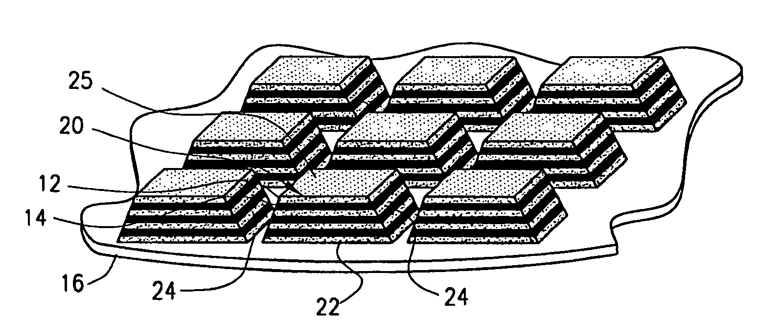
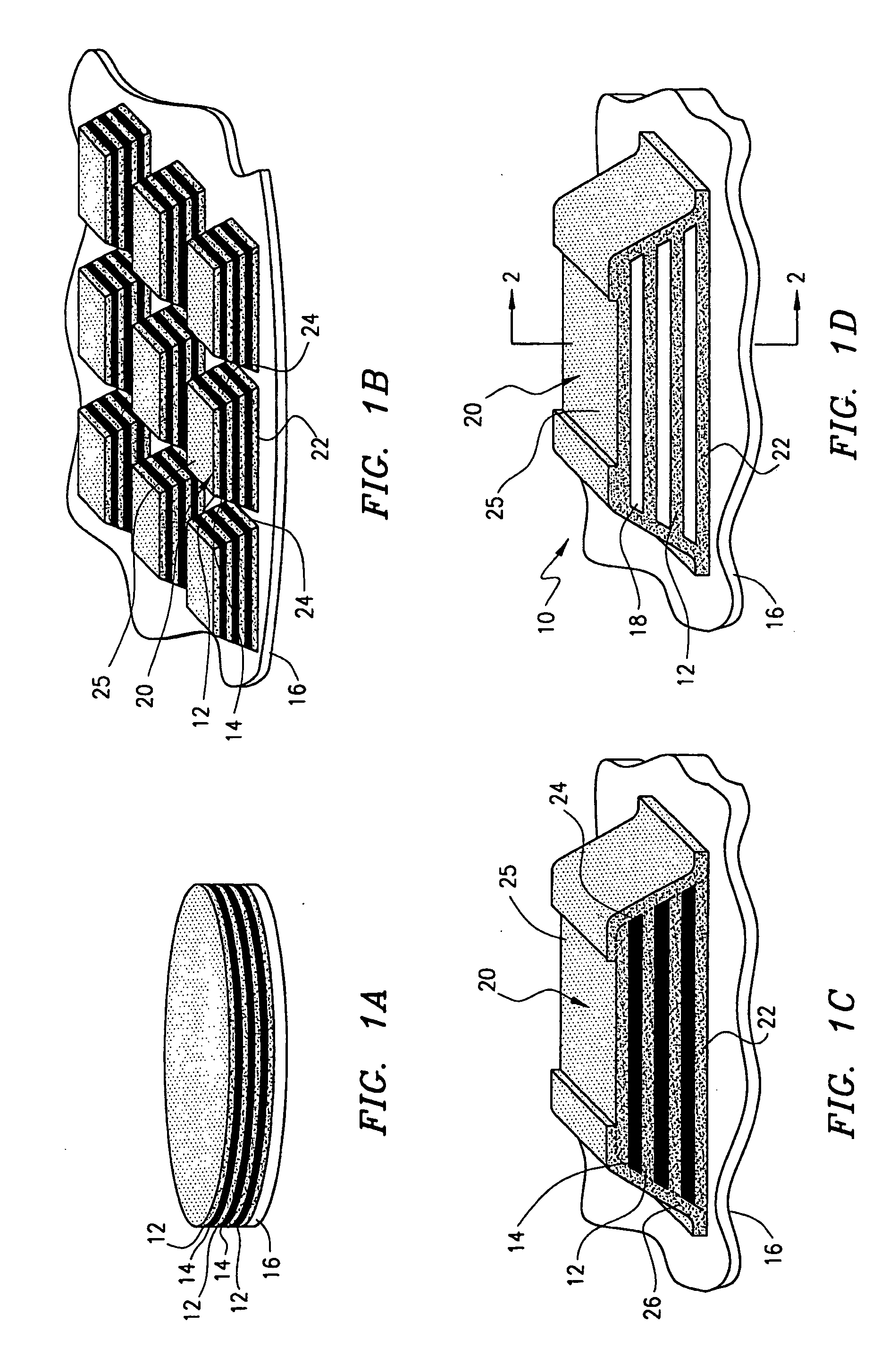
[0022]FIGS. 1A-1D depict stages in the fabrication of an exemplary distributed Bragg reflector 10 in accordance with this invention. Referring first to FIG. 1A, the Bragg reflector 10 is formed by growing or depositing alternating structure layers 12 and sacrificial layers 14 onto a substrate 16. The outermost layer is preferably a structure layer 12, and the number of layers will depend on the reflectivity and stop band required of the Bragg reflector 10. For example, the layers 12 could comprise as little as one sacrificial layer 14 and one structure layer 12 if the required reflectivity was low. The layers 12, 14 are preferably substantially parallel to each other. The thickness of the layers 12, 1...


PUM


Abstract

A distributed Bragg reflector and a method of fabricating the same incorporates a support for supporting the gaps against collapse. The method includes forming a plurality of alternating structure and sacrificial layers on a substrate. The structure and sacrificial layers are etched into at least one mesa protruding from the substrate. A support layer is formed on the at least one mesa leaving a portion of the structure and sacrificial layers exposed. At least a portion of at least one of the exposed sacrificial layers are etched from between the structure layers to form gaps between the structure layers.

Description

BACKGROUND OF THE INVENTION [0001] 1. Technical Field of the Invention [0002] The present invention relates in general to optical devices, and more particularly to distributed Bragg reflectors and their fabrication. [0003] 2. Description of Related Art [0004] A distributed Bragg reflector (DBR) is a periodic grating that, in a semiconductor system, can be monolithically formed on a wafer from alternating layers of differing index of refraction. DBRs have applications in various optic devices, in part because DBRs can achieve a high reflectivity in a relatively compact space. Further, DBRs can be tested immediately after fabrication on a wafer, unlike a crystalline reflector that must be cleaved prior to testing. Examples of devices that have incorporated DBRs include tunable optic filters, tunable detectors, and surface emitting lasers including vertical cavity surface emitting lasers (VCSEL). [0005] The reflectivity of a DBR is a function of both its geometry and the relative diffe...

Claims


Application Information

Patent Timeline
IPC IPC(8): G02B1/10
CPCH01S5/18363H01S5/18341
Inventor CORZINE, SCOTT W.TAN, MICHAEL RENNE TYLIN, CHAO KUNZHU, JINTIANLEARY, MICHAEL H.
Owner CORZINE SCOTT W
Features
  • R&D
  • Intellectual Property
  • Life Sciences
  • Materials
  • Tech Scout
  • Unparalleled Data Quality
  • Higher Quality Content
  • 60% Fewer Hallucinations
Learn More