Method to build robust mechanical structures on substrate surfaces

a technology of mechanical structure and substrate surface, which is applied in the direction of photomechanical apparatus, instruments, and semiconductor/solid-state device details, etc., can solve the problems of unable to manufacture robust parts, catastrophic failure of the connection of the seed layer to the substrate surface, and more likely to occur peeling or breaking of the metal seed layer from the substrate, etc., to achieve the effect of robust mechanical structur

Inactive Publication Date: 2007-08-07
FORMFACTOR INC
View PDF12 Cites 22 Cited by
  • Summary
  • Abstract
  • Description
  • Claims
  • Application Information

AI Technical Summary

Benefits of technology

[0010]In accordance with the present invention, a robust mechanical structure is provided to prevent mechanical structures formed on a substrate from detaching from the substrate surface.
[0011]The strengthened structure is formed by plating an additional metal layer on a metal seed layer to form a foundation, and then embedding the plated foundation structure in an adhesive material, such as epoxy or filled epoxy. Components, such as probe springs, can then be constructed on the deposited foundation, or transferred by soldering or mass joining to the foundation. The adhesive material forms a structure serving to improve mechanical robustness by counteracting forces applied to elements formed on or attached to the foundation to prevent the foundation from detaching from the substrate on which it is formed.

Problems solved by technology

As the size of the bond pad shrinks to accommodate smaller structures such as MEMS, or to accommodate limited spacing between small structures in an array, peeling or breaking of the metal seed layer from the substrate is more likely to occur, particularly with significant forces applied to mechanical structures formed on the bond pad.
Minor changes in processing conditions such as hydration / dehydration conditions can cause deterioration of the adhesion strength between the seed layer and the substrate, leading to catastrophic failure of the seed layer connection to the substrate surface.
In some cases, robust parts cannot be fabricated as the peel strength required for such robust structures exceeds the adhesion strength of the seed layer to the substrate on which it is formed.

Method used


Image

  • Method to build robust mechanical structures on substrate surfaces
  • Method to build robust mechanical structures on substrate surfaces
  • Method to build robust mechanical structures on substrate surfaces

Examples


Embodiment Construction

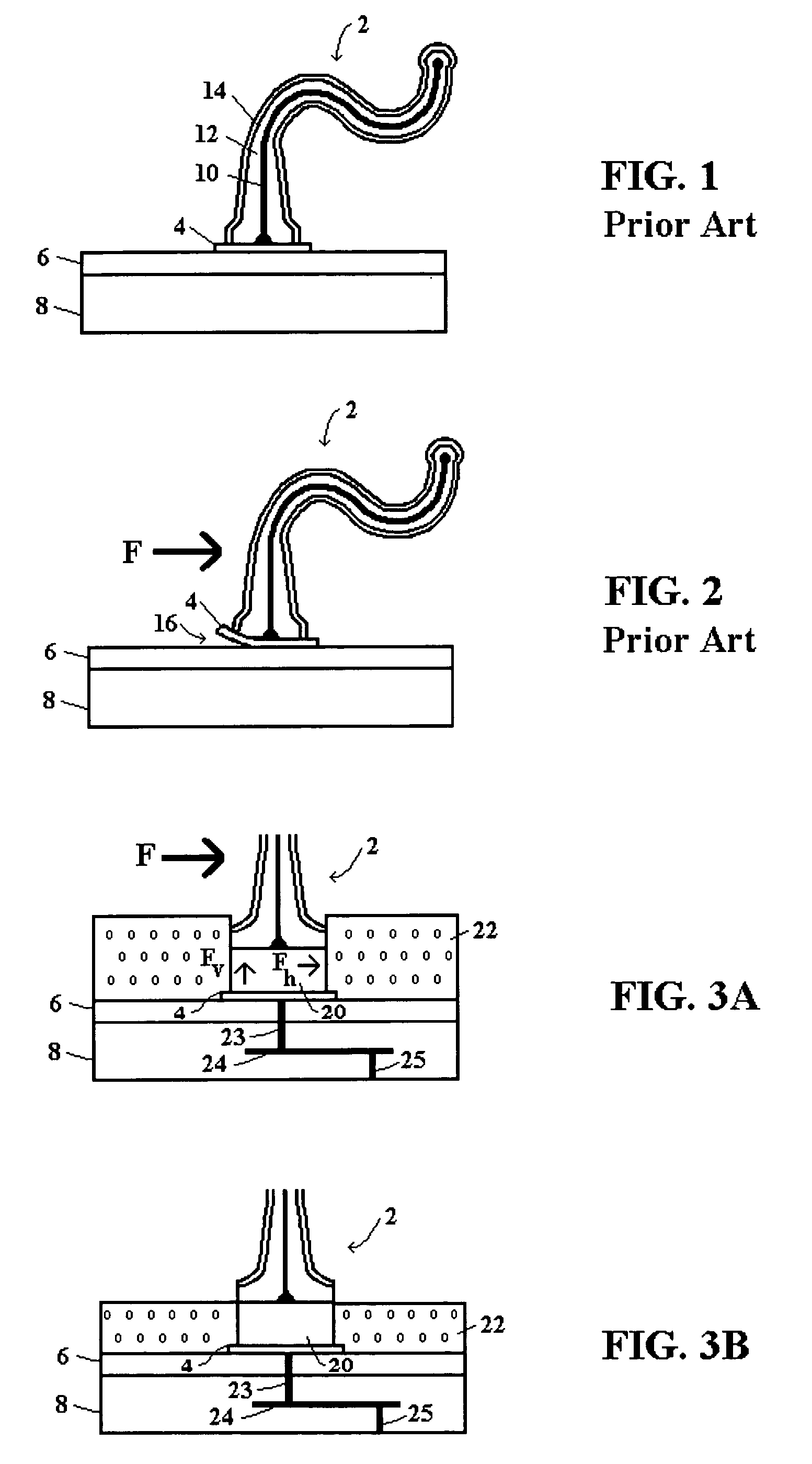
[0032]FIG. 3A illustrates a robust mechanical structure for supporting spring probes according to the present invention, including a foundation formed over a bond pad 4 for supporting a spring probe 2, a reinforcing insulation layer 22 provided around the foundation, and application of a force F to a spring probe 2 formed on the foundation. FIG. 3A includes a substrate 8 with a insulation coating layer 6 and a metal seed layer bond pad 4 formed on the layer 6, as described in FIGS. 1-2. In FIG. 3A, components carried over from FIGS. 1 and 2 are similarly labeled, as will be components carried over in subsequent drawings.

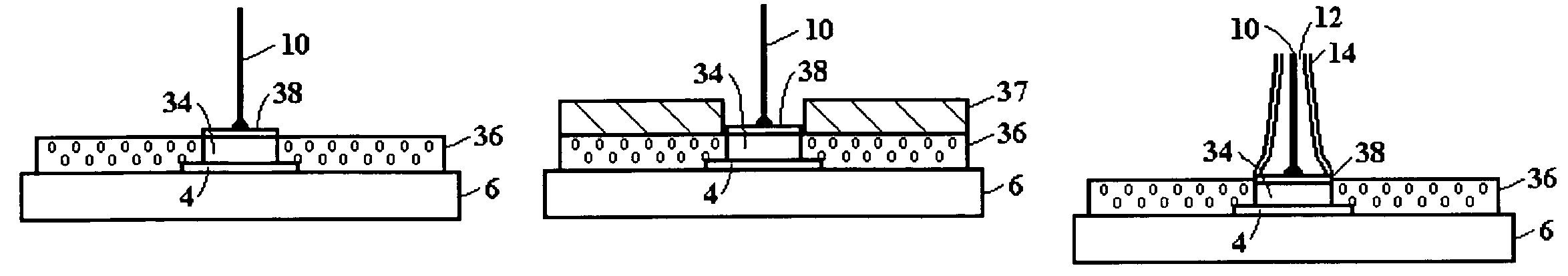
[0033]To provide the foundation, FIG. 3A includes a metal plating layer 20 applied over the metal seed layer 4. The spring probe 2 is shown constructed on the metal plating layer 20. A dielectric material 22 is provided over the exposed polymer surface 6, around the edges of the metal seed layer pad 4, around the edges of the metal plating layer 20, on a portion of t...


PUM

PropertyMeasurementUnit
adhesiveaaaaaaaaaa
resilientaaaaaaaaaa
mechanical structureaaaaaaaaaa

Abstract

A robust mechanical structure is provided to prevent small foundation structures formed on a substrate from detaching from the substrate surface. The strengthened structure is formed by plating a foundation metal layer on a seed layer and then embedding the plated foundation structure in an adhesive polymer material, such as epoxy. Components, such as spring probes, can then be constructed on the plated foundation. The adhesive polymer material better assures the adhesion of the metal foundation structure to the substrate surface by counteracting forces applied to an element, such as a spring probe, attached to the plated foundation.

Description

BACKGROUND[0001]1. Technical Field[0002]The present invention relates in general to fabrication of a mechanical structure on a substrate surface for robustly mounting Micro Electro Mechanical Systems (MEMS). More particularly, the present invention relates to a structure provided on a substrate surface for robustly mounting spring probes used on probe cards for testing integrated circuits on wafers.[0003]2. Related Art[0004]Mechanical structures are fabricated on substrate surfaces for a variety of applications. The substrate surfaces include polymers, metals, ceramics, semiconductors, etc. Typically to make electrical contact, a metal seed layer is deposited on the substrate surface to form bond pads for mounting the mechanical structures. As the size of the bond pad shrinks to accommodate smaller structures such as MEMS, or to accommodate limited spacing between small structures in an array, peeling or breaking of the metal seed layer from the substrate is more likely to occur, pa...

Claims


Application Information

Patent Timeline
Patent Type & Authority Patents(United States)
IPC IPC(8): H01R9/00B32B9/00B32B15/04
CPCH01L24/80G01R3/00G01R1/06716Y10T29/49117H01L2924/01013H01L2924/01029H01L2924/01033H01L2924/01046H01L2924/01078H01L2924/01079H01L2924/01082H01L2924/01005H01L2924/01006H01L2924/01023H01L2924/01047H01L2924/01074H01L2924/014G01R1/06744H01L2924/1461Y10T428/12347Y10T156/10Y10T29/49147Y10T428/12556Y10T428/12535Y10T428/12569Y10T428/12542Y10T428/12375H01L2924/00H01L2924/14Y10T428/31681H01L23/48
Inventor GRUBE, GARY W.MATHIEU, GAETAN L.ELDRIDGE, BENJAMIN N.SOFIELD, CHADWICK D.
Owner FORMFACTOR INC
Why Eureka
Try Eureka